
Product observation and measurement method based on five cameras

An observation and measurement, five-camera technology, applied in the field of product observation and measurement based on five cameras, can solve the problems of pasting chip inspection, inability to fully understand and eliminate product quality abnormalities, low production efficiency, etc., to achieve convenient use and efficient observation. , to avoid the effect of low production efficiency

Inactive Publication Date: 2017-08-25
上海功源电子科技有限公司
View PDF0 Cites 1 Cited by
  • Summary
  • Abstract
  • Description
  • Claims
  • Application Information

AI Technical Summary

Problems solved by technology

[0004] However, the traditional optical inspection method only has an optical microscope or camera that is installed on the top (Top View) facing the chip. With this inspection method, only two-dimensional (planar) inspection of the chip and the bonding wire can be performed, and the paste The side of the chip (three-dimensional) is inspected, such as: the height of the silver glue, the shape and height of the bonding wire, the size and shape of the small balls that are bonded to the first solder joint and the second solder joint, etc. for a comprehensive inspection. It is impossible to fully understand and eliminate the problems that cause abnormal quality in product production
[0005] Another traditional optical inspection method uses a manual or electric-driven rotating single-sided prism to observe each side of the product in turn. Its limitations are mainly reflected in the fact that it cannot follow the size of the product. Conditions and imaging positions are mutually restrained, and the product cannot be comprehensively observed and measured from the top, front, back, left, and right directions at the same time, and the production efficiency is low.

Method used


Image

  • Product observation and measurement method based on five cameras

Examples


Embodiment Construction

[0014] The present invention is described in detail below in conjunction with accompanying drawing and specific embodiment:

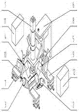
[0015] Such as figure 1 shows a product observation and measurement method based on five cameras, which includes a top camera 1, a right camera 2, a front camera 3, a left camera 4, a rear camera 5, a top camera adjustment frame 6, an XY slide table 7, and a Z axis 8. Camera fixing plate 9, camera fixing frame 10, main control computer 11, sub-controlling computer 12, described XY slide table 7, Z axis 8, camera fixing plate 9, camera fixing frame 10 are 4 pieces, described The top camera 1, the right camera 2, the front camera 3, the left camera 4, and the rear camera 5 have their own independently adjustable optical systems.

[0016] Working process of the present invention is as follows:

[0017] Adjustments when using this method for the first time and when changing products:

[0018] Turn on the main control computer 11, put the product directly...


PUM


Abstract

The invention discloses a product observation and measurement method based on five cameras, and the method is characterized in that the method employs a top camera, a right camera, a front camera, a left camera, a rear camera, a top camera adjustment frame, an XY sliding table, a Z-axis, a camera fixing plate, a camera fixing frame, a main control computer, and branch control computers; the five cameras respectively have an optical system which can be adjusted independently, and can independently carry out the imaging, position adjustment and independent focusing. The five cameras can independently carry out the collection of the images of the top surface, front side surface, rear side surface, left side surface and right side surface of a product, and carry out the observation and measurement of the collected images. The branch control computers enable the observation and measurement results of the images collected by the right camera, the front camera, the left camera and the rear camera to be transmitted to a main control computer. The main control computer enables the observation and measurement results transmitted by the branch control computers, along with the observation and measurement result of the image collected by the top camera, to be combined to form a complete product detection report, and stores the report in the main control computer.

Description

technical field [0001] The invention relates to a product observation and measurement method, in particular to a product observation and measurement method based on five cameras. Background technique [0002] In the semiconductor packaging industry, the purpose of die bonding is to place the separated die (Die) on the leadframe (leadframe) or substrate (PCB) and fix it with silver glue (epoxy). The lead frame or substrate provides a sticking position for the die (die pad), and is preset with extension feet or pads (pads) that can extend the IC die circuit. The purpose of the wire bonding is to connect the contacts on the die to the pins on the lead frame or substrate with extremely thin gold wires (18~50μm), so as to transmit the circuit signal of the IC die to the outside world. When soldering wires, use the contact point on the die as the first soldering point, and the soldering point on the inner pin as the second soldering point. Firstly, the ends of the gold wires are...

Claims


Application Information

Patent Timeline
IPC IPC(8): G01D21/02
CPCG01D21/02
Inventor 卢冬青
Owner 上海功源电子科技有限公司
Learn More