Acousto-optic modulator, method for improving output light energy of acousto-optic modulator and laser
An acousto-optic modulator and laser technology, applied in the field of lasers, can solve problems such as leakage light and energy waste, and achieve the effect of improving energy conversion rate and utilization rate
- Summary
- Abstract
- Description
- Claims
- Application Information
AI Technical Summary
Problems solved by technology
Method used
Image

Examples
Embodiment 1
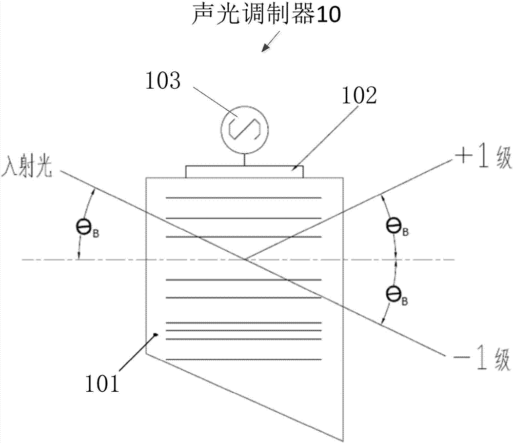
[0037] figure 1 It is a schematic diagram of an acousto-optic modulator according to an embodiment of the present invention. Such as figure 1 As shown, the acousto-optic modulator 10 includes an acousto-optic crystal 101 , a piezoelectric transducer 102 and a driving power source 103 . The electrical signal of the driving power supply 103 drives the piezoelectric transducer. When the AOM 10 has a pulse signal, that is, when the pulse signal is at a high level, the refractive index of the acousto-optic crystal in the AOM will change from density to density. form a raster. At this time, if the incident light passes through the acousto-optic crystal at the Bragg angle θB, diffraction will occur, causing the light to be deflected and deviate from the original propagation direction, and the deflected light is +1 order light. When the acousto-optic modulator has no pulse signal, that is, when the pulse signal is at a low level, the refractive index of the acousto-optic crystal wi...
Embodiment 2
[0053] Figure 6 It is a schematic diagram of the optical path of the laser 200 according to the embodiment of the present invention. The laser 200 is a Q-switched fiber laser, and its optical path structure is composed of four parts. The first part is LD, that is, the pump source 210, which is used to provide the energy required for the first-stage amplification; the second part is the first-stage amplification optical path 220, usually It consists of a section of gain fiber, which is used to convert the pump light output by the pump source 210 into signal light, and amplifies the signal light at the same time; the third part is an acousto-optic modulator 230, which is used to adjust the pulse width. The third part is the secondary amplification optical circuit 240, which is used to amplify the signal light again, so that the energy of the signal light reaches a certain energy value; the fifth part is the output optical isolator 250, which is used to output the signal light w...
Embodiment 3
[0060] Figure 7 It is a flow chart of a method for increasing output light energy of an acousto-optic modulator according to an embodiment of the present invention. Such as Figure 7 As shown, in the method for improving the output light energy of the AOM, the AOM includes an AOM crystal, and the AOM also includes a -1-level collimator, a +1-level collimator, and a time delay An optical fiber and a beam combiner; the method comprising:
[0061] Step 301: Incident light enters the acousto-optic crystal and emits -1 order light and +1 order light respectively;
[0062] Step 302: the -1-level collimator receives -1-level light; the +1-level collimator receives +1-level light;
[0063] Step 303: Connect the delay fiber to the output direction of the +1-level collimator so that the +1-level light is delayed for a preset time and coincides with the -1-level light in timing, and the delay fiber is collimated with the -1-level light The output direction of the beam combiner is co...
PUM
 Abstract
Description
Claims
Application Information