Mucus absorption device for highrespiratory tract

An absorption device and upper respiratory tract technology, applied in the direction of suction containers, suction devices, hypodermic injection devices, etc., can solve the problems of difficulty in realization, heavy device weight, complex structure of mucus suction tube, etc., and achieve the effect of convenient use and simple structure

Inactive Publication Date: 2017-08-29
王镜銮
View PDF8 Cites 0 Cited by
  • Summary
  • Abstract
  • Description
  • Claims
  • Application Information

AI Technical Summary

Problems solved by technology

The traditional mucus straw is combined with a negative pressure system. The structure of the mucus straw itself is complex and bulky. It is very unrealistic to equip this kind of mucus straw whether it is an emergency room or a family or school to deal with emergencies.
The prior art, such as Chinese patent 201010297841.5, discloses a sputum suction device, which connects the suction pipe to the air compressor to provide local negative pressure in the way of sucking back. The operation needs to be energized and the vacuum degree adjusted in advance. Not only is the equipment installation troublesome, And the operation is very cumbersome, although it provides a relatively ideal absorption effect, it is difficult to popularize and use; Chinese patent 201310692877.7 discloses a mucus absorption machine, the motor is placed in a circular portable surgery, and the exhaust fan is driven by a V-belt To absorb mucus in the respiratory tract, although the complex structure is integrated in the surgery, it still needs to provide power to the motor, and the internal structure is complicated, and the weight of the whole device is very heavy, so it is difficult to achieve the technical purpose of the proposed operation; Chinese patent 201610728576.9 discloses a manual Respiratory mucus suction equipment uses a principle similar to a large-volume syringe to extract mucus from the upper respiratory tract. Although the structure is simple, there is no flow-limiting device in the middle of the entire structure. The extracted air and mucus are mixed together. There is no way to achieve continuous operation. The reciprocating operation of extracting and pressing out is not only complicated to operate, but also has great potential safety hazards
However, after sudden phlegm congestion causes dyspnea, if not treated in time, the consequences are often very serious. Therefore, a simple mucus absorption device that is easy to equip and carry is needed to facilitate different environments to deal with such sudden and strong symptoms.

Method used


Image

  • Mucus absorption device for highrespiratory tract
  • Mucus absorption device for highrespiratory tract
  • Mucus absorption device for highrespiratory tract

Examples


Embodiment approach 1

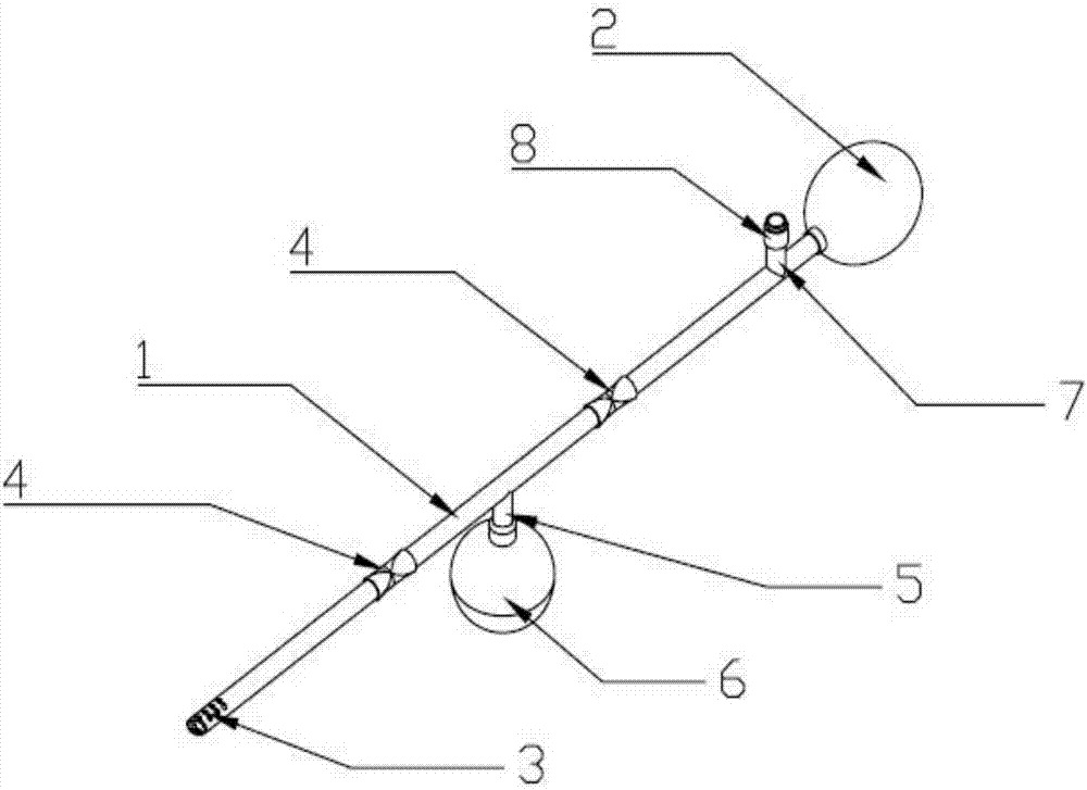
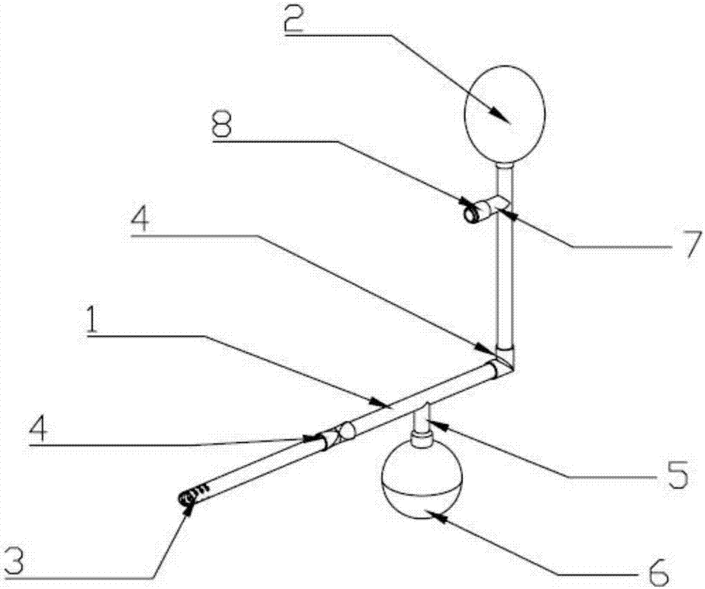
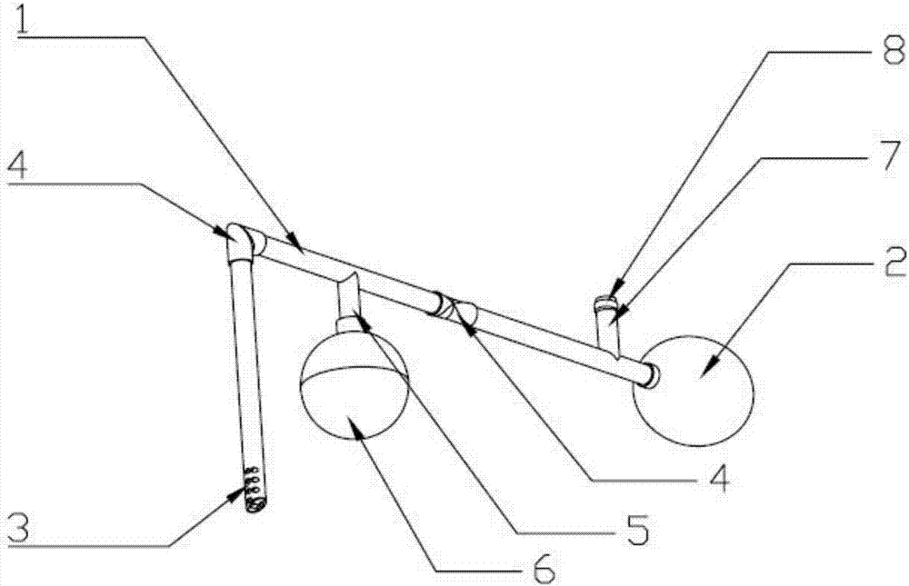
[0023] Implementation mode 1: if Figures 1 to 6 As shown, the upper airway mucus absorption device includes a suction pipe 1 and a pressure ball 2 connected to the tail end of the suction pipe 1. Two sections of half-hose 4, the half-hose 4 is provided with creases, when the half-hose 4 has a folding angle ≥ 90°, the half-hose 4 is closed, when the half-hose 4 is straightened, the half-hose 4 conduction, a branch pipe 5 is provided between the two halves of the hose 4, the branch pipe 5 is connected with a sputum storage device 6, and an exhaust pipe 7 is provided at the joint between the tail end of the suction pipe 1 and the pressure ball 2, and the exhaust pipe 7 is provided with a There is one-way valve 8. The sputum storage device 6 is detachably connected to the branch pipe 5, and the lower part of the sputum storage device 6 can be unscrewed. There is a detachable connection between the half hose 4 and the suction pipe 1 . The half hose is made of PVC material, has ...

Embodiment approach 2

[0024] Implementation mode 2: if Figure 7 As shown, the upper airway mucus absorption device includes a suction pipe 1 and a pressure ball 2 connected to the tail end of the suction pipe 1. The front end of the suction pipe 1 is a blunt end, and several through holes 3 are evenly distributed on the side wall. There are two valves 9, and a branch pipe 5 is arranged between the two valves 9. The branch pipe 5 is connected with a sputum storage device 6. An exhaust pipe 7 is arranged at the connection between the tail end of the suction pipe 1 and the pressure ball 2. On the exhaust pipe 7 A one-way valve 8 is provided. The sputum storage device 6 is detachably connected to the branch pipe 5, and the lower part of the sputum storage device 6 can be unscrewed. Be detachable connection between valve 9 and suction pipe 1. How to use: close the valve 9 near the pressure ball 2, squeeze the pressure ball 2, and exhaust the air under the action of the one-way valve 8, the part of th...


PUM


Abstract

The invention relates to a respiratory medical instrument, in particular to a mucus absorption device for a highrespiratory tract. In a traditional sputum aspirator, a suction pipe cooperates with a negative pressure system, the structure of the traditional sputum aspirator is complicated and cumbersome, and whether an emergency house call is made or an emergency situation is handled in a family or a school, it is very impractical to use the sputum aspirator. The mucus absorption device for the highrespiratory tract comprises a suction pipe and a stress ball connected to the tail end of the suction pipe; the front end of the suction pipe is a blunt end, and a plurality of through holes are evenly formed in the side wall of the suction pipe; two segments of half hoses are arranged on the suction pipe, and creases are arranged on the half hoses; when folded angles of the half hoses are >= 90 degrees, the half hoses are closed, and when the half hoses are pulled straight, the half hoses are communicated with each other; a branch pipe is arranged between the half hoses and is connected with a sputum storage device; a vent pipe is arranged in the position where the tail end of the suction pipe is connected with the stress ball, and a check valve is arranged on the vent pipe. According to the mucus absorption device for the highrespiratory tract, the structure is simple, use is convenient, convenience is brought to emergency situation handling, and the device is widely suitable for an emergency call and use in a family or a school.

Description

technical field [0001] The invention relates to a respiratory medical device, in particular to an upper respiratory tract mucus absorption device. Background technique [0002] Clinically, the nose, pharynx, and larynx are collectively referred to as the upper respiratory tract. Obstruction of the airway by mucus in the upper airway can cause breathing difficulties and even suffocation, and is the most common symptom of respiratory diseases. The traditional mucus straw is combined with a negative pressure system. The structure of the mucus straw itself is complex and bulky. It is very unrealistic to equip this kind of mucus straw whether it is an emergency room or a family or school to deal with emergencies. The prior art, such as Chinese patent 201010297841.5, discloses a sputum suction device, which connects the suction pipe to the air compressor to provide local negative pressure in the way of sucking back. The operation needs to be energized and the vacuum degree adjust...

Claims


Application Information

Patent Timeline
Patent Type & Authority Applications(China)
IPC IPC(8): A61M1/00
CPCA61M1/0001A61M1/0023A61M1/82A61M1/84
Inventor 王镜銮
Owner 王镜銮
Why Eureka
Try Eureka