Broadband radar wave signal generating structure and method

A broadband radar and waveform signal technology, applied in the field of broadband radar waveform signal generation structure, can solve the problems of complex signal generation circuit, high local oscillator complexity, low intermediate frequency signal frequency, etc. Wide frequency range

Active Publication Date: 2017-08-29
LEIHUA ELECTRONICS TECH RES INST AVIATION IND OF CHINA
View PDF6 Cites 13 Cited by
  • Summary
  • Abstract
  • Description
  • Claims
  • Application Information

AI Technical Summary

Problems solved by technology

Therefore, there are several disadvantages in the prior art: (1) the complexity of the local oscillator is high (2) the signal generation circuit is complicated
(3) The frequency of the intermediate frequency signal generated by DDS is low

Method used


Image

  • Broadband radar wave signal generating structure and method
  • Broadband radar wave signal generating structure and method
  • Broadband radar wave signal generating structure and method

Examples


Embodiment Construction

[0019] In order to make the objectives, technical solutions and advantages of the present invention clearer, the technical solutions in the embodiments of the present invention will be described in more detail below in conjunction with the drawings in the embodiments of the present invention. In the drawings, the same or similar reference numerals denote the same or similar elements or elements having the same or similar functions throughout. The described embodiments are some, but not all, embodiments of the invention. The embodiments described below by referring to the figures are exemplary and are intended to explain the present invention and should not be construed as limiting the present invention. Based on the embodiments of the present invention, all other embodiments obtained by persons of ordinary skill in the art without creative efforts fall within the protection scope of the present invention.

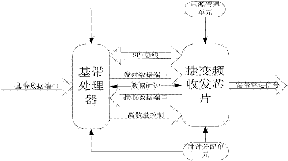
[0020] The structure and method for generating wideband radar wavefor...


PUM


Abstract

The invention provides a broadband radar wave signal generating structure and method; the structure comprises a baseband processor, a frequency-agile transceiving chip, a power management unit and a clock distribution unit; the baseband processor is completed by an FPGA (field-programmable gate array) chip, the frequency-agile transceiving chip is initially configured through an SPI (serial peripheral interface) bus, a radar baseband signal is generated as required, the signal is transmitted to the frequency-agile transceiving chip through a transmitting data port, and the power management unit employs a voltage stabilizer to generate voltages required by the baseband processor and the frequency-agile transceiving chip. Radar signals up to 6 GHz in frequency are generated herein through the single frequency-agile transceiving chip along with FPGA hardware architecture, a subsequent variable-frequency circuit is simplified, large-bandwidth frequency hopping feature is achieved, and the design complexity of a local oscillator circuit is decreased.

Description

technical field [0001] The invention belongs to the technical field of radar signal generation, and in particular relates to a structure and method for generating a broadband radar waveform signal. Background technique [0002] The main waveform signal forms of radar applications are narrow-band pulse signals and pulse chirp signals. The generation is generally composed of several parts such as intermediate frequency waveform generation, frequency up-conversion and power amplification. At present, radar IF waveform generation generally adopts DDS chips to directly generate IF signals, and then uses dual local oscillator signals to generate RF signals after twice up-conversion and several filters, amplifiers and other circuits. Radar signals require a wide working bandwidth, which is usually accomplished by local oscillator frequency hopping. The number of frequency hopping determines the complexity of local oscillator signal generation. The more frequency hopping points, the...

Claims


Application Information

Patent Timeline
Patent Type & Authority Applications(China)
IPC IPC(8): G01S7/02
CPCG01S7/02
Inventor 包可佳唐琦郭薇
Owner LEIHUA ELECTRONICS TECH RES INST AVIATION IND OF CHINA
Why Eureka
Try Eureka