
Battery temperature control device and battery temperature control system

A battery temperature regulation and battery technology, applied in electric power devices, batteries, secondary batteries, etc., can solve the problems of increased refrigerant power consumption, battery cell temperature fluctuations, and shorter vehicle driving distances, and achieve heat transfer efficiency. The effect of improving, improving the efficiency of temperature regulation, and reducing power consumption

Active Publication Date: 2017-08-29
FURUKAWA ELECTRIC CO LTD +1
View PDF13 Cites 3 Cited by
  • Summary
  • Abstract
  • Description
  • Claims
  • Application Information

AI Technical Summary

Problems solved by technology

[0003] However, in Patent Document 1, there is a problem that although the battery is cooled by supplying the air cooled by the refrigerant to the battery, the heat transfer efficiency is insufficient due to the passage of the air.
Furthermore, in Patent Document 1, there is also the following problem: it is difficult to make the air flow uniform, so due to the difference in the path of the air (for example, the difference between the upstream side and the downstream side of the air flow), air flow to each battery cell (battery cell) constituting the battery ) The temperature of the air supplied will vary, so that the cooling of the battery takes time and the temperature of the battery cells will fluctuate
[0008] However, in the system of Patent Document 3 in which the same cooling system core is provided and cooling is performed, the mass of the vehicle and the power consumption for cooling the refrigerant increase, so there is still a problem that the running distance of the vehicle becomes shorter.

Method used


Image

  • Battery temperature control device and battery temperature control system
  • Battery temperature control device and battery temperature control system
  • Battery temperature control device and battery temperature control system

Examples


Embodiment Construction

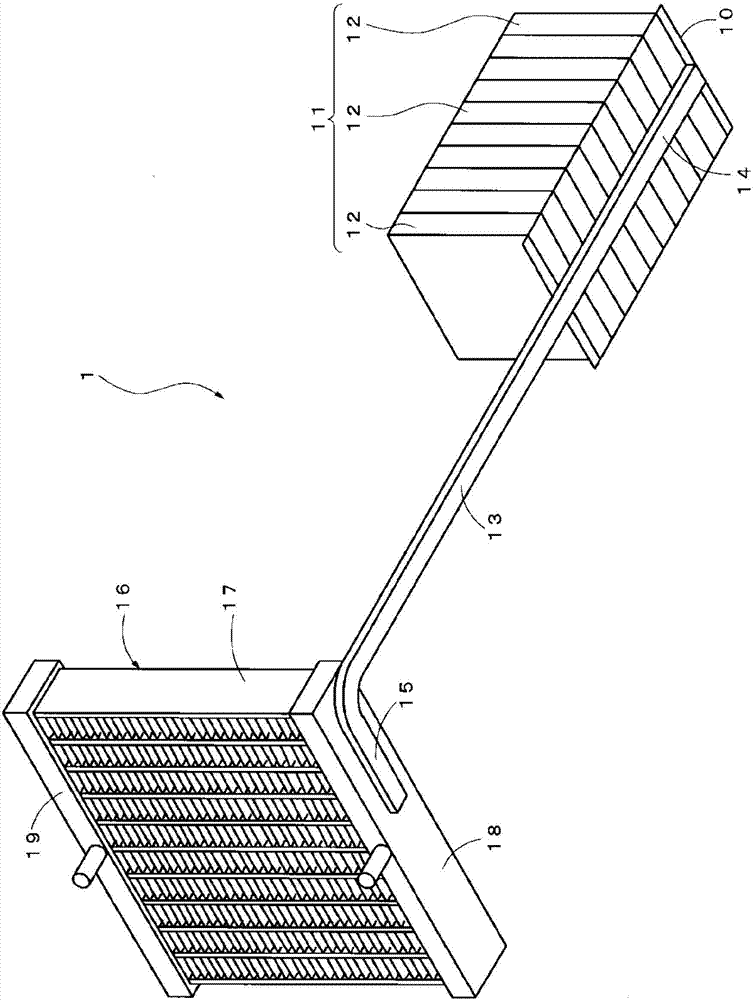
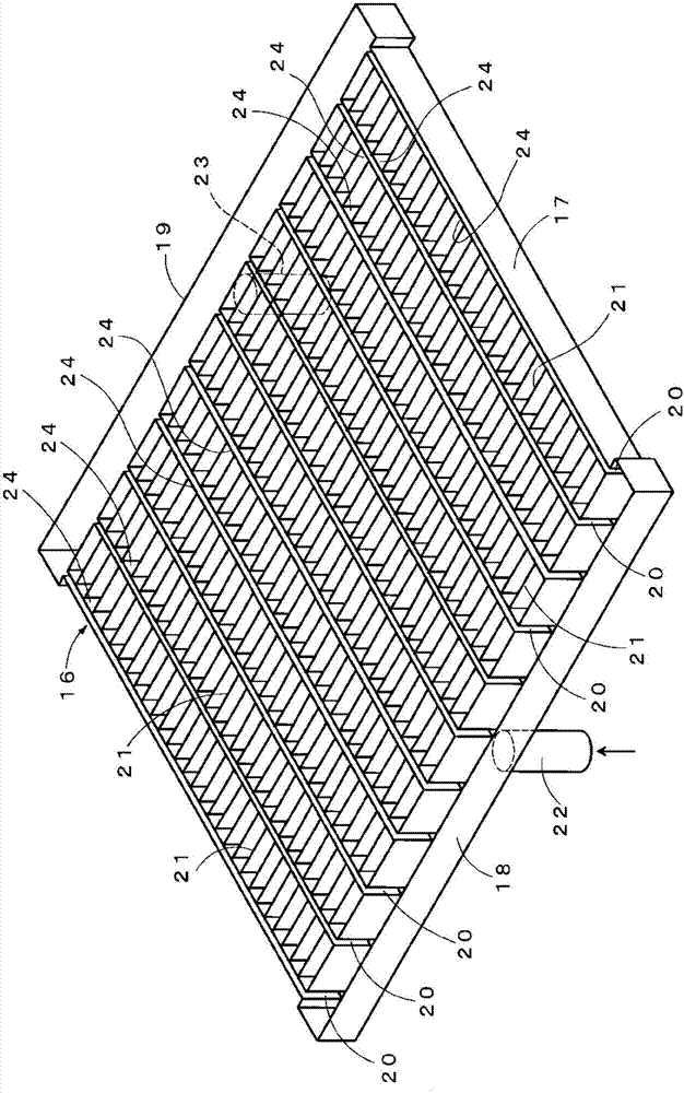
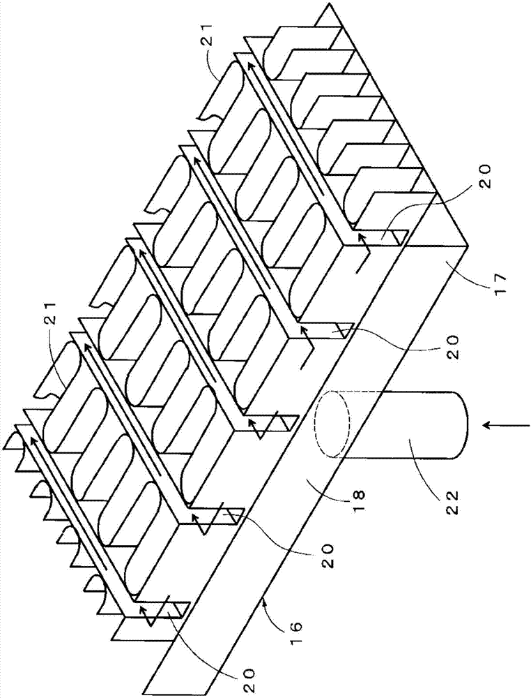
[0052] Hereinafter, the battery temperature adjustment system according to the first embodiment of the present invention will be described with reference to the drawings. Such as figure 1 As shown, the battery temperature regulation system 1 involved in the first embodiment includes: a battery 11 having a plurality of battery cells 12; a heat pipe 13 thermally connected to the battery 11 through an end 14; and an evaporator (heat pump) The evaporator) 16 is directly connected to the other end 15 of the heat pipe 13 so as to be thermally connected with the heat pipe 13 . That is to say, the evaporator 16 is in direct contact with the other end 15 of the heat pipe 13 .

[0053] The battery 11 includes a heat receiving plate 10 in contact with the side surface of each battery cell 12 . The surface of the heat receiving plate 10 is in contact with the side surface of the battery cell 12 , so that the heat receiving plate 10 and the battery cell 12 are thermally connected. In ad...


PUM


Abstract

Provided are a battery temperature control device and a battery temperature control system, having excellent heat-transfer efficiency and uniformity of temperature controlling ability, and being configured such that an increase in mass and power consumption can be prevented. The battery temperature control device and the battery temperature control system each comprise a battery having a battery cell, a heat conduction member thermally connected at one extremity portion thereof to the battery, and condenser fins and / or an evaporator thermally connected to the heat conduction member at the other extremity portion thereof.

Description

technical field [0001] The present invention relates to a battery temperature regulating device and a battery temperature regulating system that use a heat conducting member to transport the heat released from a battery to a fin of a condenser and / or an evaporator. Background technique [0002] As a conventional battery temperature control system, a system has been proposed that includes: a battery installed in a vehicle for driving; a blower that generates air blown to the battery provided separately from the blower for an air conditioner in the vehicle compartment; A heat exchanger installed separately from the heat exchanger for the air conditioner in the cabin to cool the blown air through heat exchange between the refrigerant flowing inside and the blown air sent to the battery, and the evaporator as a heat exchanger and the In-cabin air conditioners share refrigerant (Patent Document 1). [0003] However, in Patent Document 1, there is a problem that although the batt...

Claims


Application Information

Patent Timeline
IPC IPC(8): H01M10/6552B60K11/02H01M10/613H01M10/615H01M10/617H01M10/625H01M10/647H01M10/6551H01M10/6563H01M10/6571H01M10/663
CPCB60K11/02H01M10/625H01M10/615H01M10/663H01M10/647H01M10/6551H01M10/6552H01M10/613B60K1/04B60K11/04B60K2001/005H01M10/6554B60H1/00278B60H1/3227B60H2001/00307H01M2220/20Y02E60/10H01M10/6571H01M10/617H01M10/6563
Inventor 平泽壮史池田匡视
Owner FURUKAWA ELECTRIC CO LTD
Learn More