A Modular Reconfigurable Snake Robot

A snake-shaped robot and modular technology, applied in the field of robotics, can solve the problems of insufficient compact structure, poor control accuracy, long control cycle, etc., and achieve the effects of improving convenience, short control cycle, and large output torque

Active Publication Date: 2020-05-26
HARBIN INST OF TECH
View PDF6 Cites 0 Cited by
  • Summary
  • Abstract
  • Description
  • Claims
  • Application Information

AI Technical Summary

Problems solved by technology

[0006] The present invention solves the existing problems of backlash, small driving force, long control period, poor control precision and insufficient compact structure in existing snake-shaped robots, and further provides a modular reconfigurable snake-shaped robot

Method used


Image

  • A Modular Reconfigurable Snake Robot
  • A Modular Reconfigurable Snake Robot
  • A Modular Reconfigurable Snake Robot

Examples


specific Embodiment approach 1

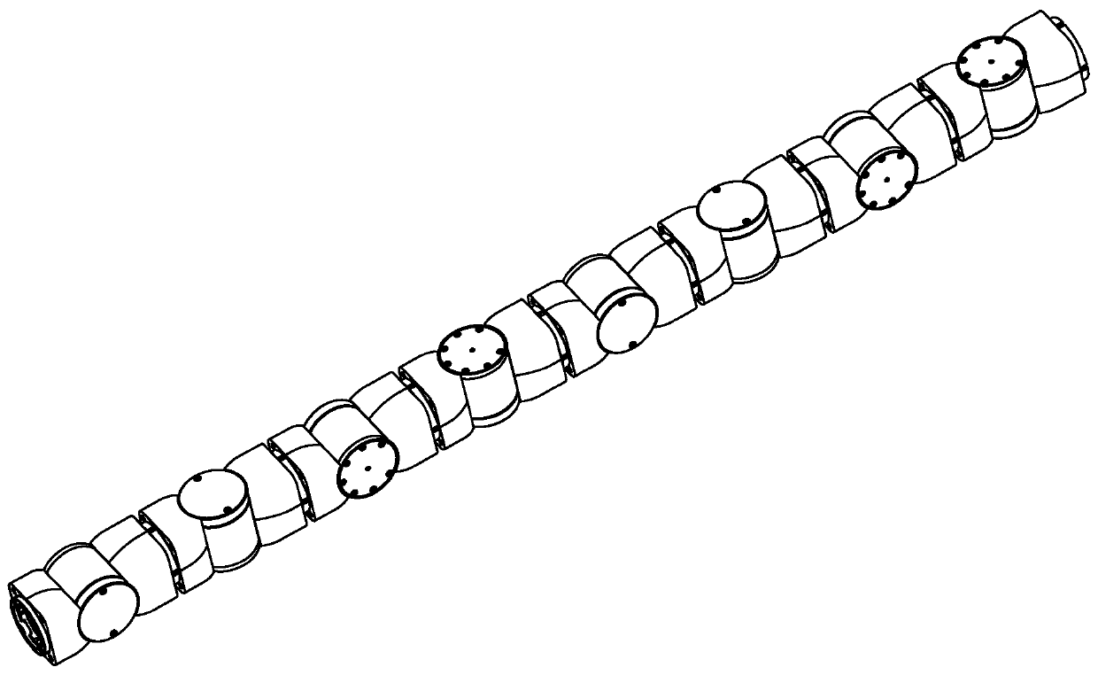
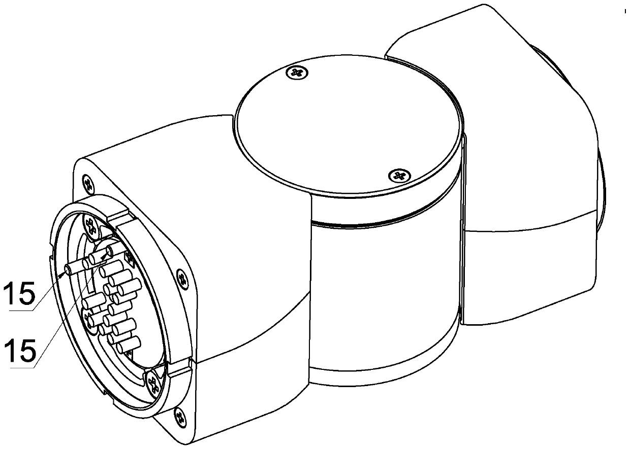
[0030] Specific implementation mode one: as Figure 1-5 As shown, the modular reconfigurable snake-like robot of this embodiment includes a plurality of modular joints connected end to end, two adjacent modular joints are rotated by 90°, and two adjacent modular joints are connected by cylindrical pins. The connection is positioned and arranged orthogonally. The modular joint includes a joint input piece, a joint output piece, an intermediate shaft section, a motor assembly and a harmonic reducer, and the two ends of the intermediate shaft section are respectively provided with a joint input piece and a joint output piece. The motor assembly and the harmonic reducer are arranged side by side inside the intermediate shaft joint, the output end of the motor assembly is connected with the harmonic reducer, the motor assembly drives the harmonic reducer to rotate, and the harmonic reducer drives the joint output Execute the swing motion with the intermediate shaft joint as the axi...

specific Embodiment approach 2

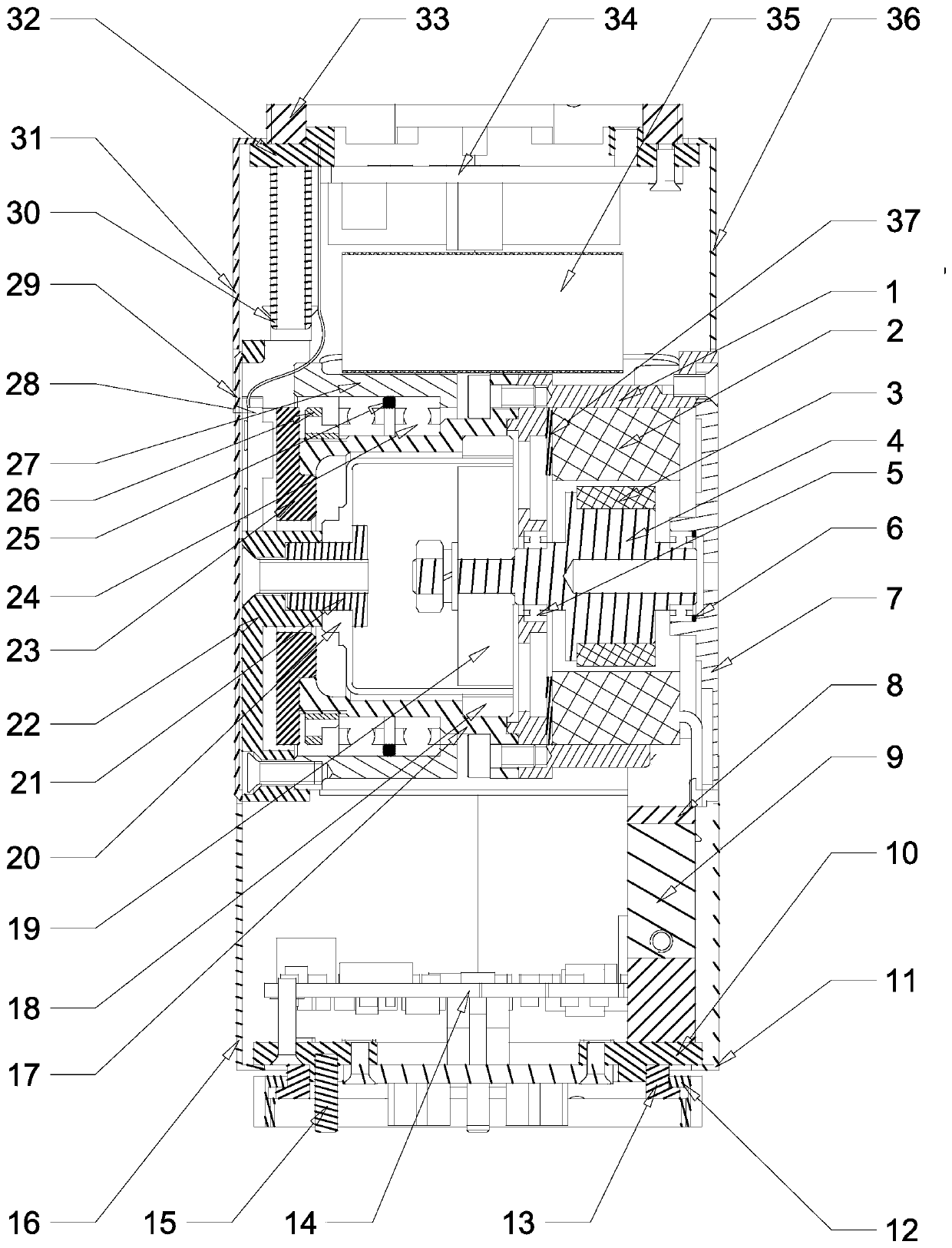
[0033] Specific implementation mode two: as figure 2 , image 3 and Figure 4 As shown, the motor assembly of this embodiment includes a motor housing 1, a motor stator 2, a motor rotor 3, a motor shaft 4 and a motor end cover 7, the motor housing 1 is a cylindrical shell, and the motor housing 1 is arranged inside the intermediate shaft joint. The motor shaft 4 is arranged inside the motor housing 1 and is connected to the motor end cover 7, the motor rotor 3 is set on the motor shaft 4, the motor stator 2 is set outside the motor rotor 3 and is fixedly installed on the inner wall of the motor housing 1, A spacer 37 is arranged between the motor casing 1 and the motor stator 2 .

[0034] In this embodiment, the motor stator 2 is fixedly connected to the motor casing 1 by glue bonding, and the motor rotor 3 is also fixedly connected to the motor shaft 4 by glue bonding. The motor shaft 4 and the first deep groove ball bearing 5 The inner ring is closely matched, and when t...

specific Embodiment approach 3

[0035] Specific implementation mode three: as image 3 As shown, the motor assembly of this embodiment also includes two first deep groove ball bearings 5 ​​and a gasket 6, the motor shaft 4 is installed in the motor housing 1 through the two first deep groove ball bearings 5, and the gasket 6 is arranged on the motor Between the end cover 7 and the first deep groove ball bearing 5 . In this way, one end of the motor shaft 4 is connected to the motor casing 1 through a deep groove ball bearing 5, and the other end of the motor shaft 4 is connected to the motor end cover 7 through another deep groove ball bearing 5, and the motor end cover 7 is arranged on on the inner wall of the intermediate shaft joint. Other components and connections are the same as those in the second embodiment.


PUM


Abstract

The invention discloses a modular reconfigurable snakelike robot, and relates to a snakelike robot. The problems that an existing snakelike robot has reverse tooth spaces and is small in driving force, long in control period, poor in control precision and not compact in structure are solved. The reconfigurable snakelike robot is formed by connecting a series of modular joints end to end. Every two adjacent modular joints are spaced by 90 degrees and are electrically connected in a spring-contact pin mode. The modular joints can achieve single-joint rotating motion in the way that a brushless DC motor drives a harmonic reducer, and the advantages of structural modularization, configuration compactness, high carrying capacity and the like are achieved. The snakelike robot can achieve separation at the adjacent joints in different working environments, and thus can be configured into two or more snakelike robots. In a similar way, two or more snakelike robots can be configured into one snakelike robot. The modular reconfigurable snakelike robot is suitable for the fields of pipeline detection, disaster relief, aerospace planet surface detection and the like.

Description

technical field [0001] The invention relates to a snake-like robot, in particular to a modular reconfigurable snake-like robot, which belongs to the technical field of robots. Background technique [0002] Compared with traditional industrial robots, snake-shaped robots have the ability to traverse narrow spaces, overcome obstacles in complex environments such as multiple obstacles, dexterous operation capabilities with super-redundant degrees of freedom, and reconfigurable capabilities in dangerous environments. It has become a hot issue in the field of robot research and has received more and more attention. Snake robots are commonly used in pipeline inspection, disaster relief, planetary surface exploration in space and space, etc. [0003] The invention patent with the application number ZL 02144565.6 discloses a modular variable structure snake robot, the invention patent with the application number 201110183015.2 discloses the crawling speed measurement method of the ...

Claims


Application Information

Patent Timeline
Patent Type & Authority Patents(China)
IPC IPC(8): B25J9/06B25J9/08
CPCB25J9/065B25J9/08
Inventor 孙永军倪风雷朱映远史士财周云虎刘伊威刘宏
Owner HARBIN INST OF TECH
Why Eureka
Try Eureka