
Time-domain analysis method for dynamic temperature difference power generation system segmented on basis of temperature difference thermocouple material

A technology of thermocouple and thermoelectric power generation, which is applied in the direction of electrical digital data processing, special data processing applications, instruments, etc., and can solve problems that cannot be used to analyze the transient process of dynamic thermoelectric power generation systems, etc.

Inactive Publication Date: 2017-09-01
NORTH CHINA UNIV OF WATER RESOURCES & ELECTRIC POWER
View PDF2 Cites 2 Cited by
  • Summary
  • Abstract
  • Description
  • Claims
  • Application Information

AI Technical Summary

Problems solved by technology

[0007] Therefore, the calculation method of the electromotive force of the thermoelectric system in the patent document CN201410189306.6 simply approximates the boundary conditions at the junction of different substances as the fluid balance at the junction, which is only applicable to the constant physical properties of the thermoelectric power generation system, and the boundary can be simply approximated In the case of equilibrium, the analysis of the steady-state linear thermoelectric system is not applicable when the thermoelectric power generation system is in an unbalanced state, that is, it cannot be used to analyze the transient process of the dynamic thermoelectric power generation system

Method used


Image

  • Time-domain analysis method for dynamic temperature difference power generation system segmented on basis of temperature difference thermocouple material
  • Time-domain analysis method for dynamic temperature difference power generation system segmented on basis of temperature difference thermocouple material
  • Time-domain analysis method for dynamic temperature difference power generation system segmented on basis of temperature difference thermocouple material

Examples


Embodiment Construction

[0053] In order to further illustrate the present invention, please refer to the accompanying drawings

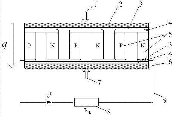
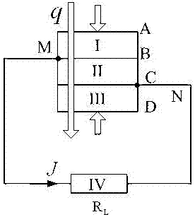
[0054] like figure 1 As shown, the thermoelectric power generation system consists of a hot end radiator 2 in contact with a heat source 1, a ceramic sheet 3, a guide sheet 4 and a pair of semiconductor thermocouples 5, a cold end radiator 6 in contact with a cold source 7, and a ceramic sheet 3 And deflector 4 composition. In order to obtain a higher electromotive force, the thermoelectric power generation system is composed of d pairs of semiconductor thermocouples 5 connected in series with the load resistor 8 through a high-conductivity guide plate 4 and a metal wire 9, and sandwiched between a thermocouple with good thermal conductivity and electrical insulation. between two ceramic sheets 3 parallel to each other. The heat flow q flows through the heat sink 2 at the hot end, the ceramic sheet 3 and the flow guide 4, d pairs with the semiconductor thermocouple 5, the...


PUM


Abstract

The invention provides a time-domain analysis method for a dynamic temperature difference power generation system segmented on the basis of a temperature difference thermocouple material. The method comprises steps as follows: firstly, a thermoelectric partial differential equation model and boundary conditions of basic physical properties of the dynamic temperature difference power generation system segmented on the basis of the temperature difference thermocouple material are established; secondly, a thermal circuit and an electric circuit of the system are more specifically analyzed and subjected to time and space discretization processing, an algebraic equation of physical quantities of internal nodes and boundary nodes of an area is established in terms of energy conservation, iteration solution is executed by starting from a time initial value, and finally, numerical solutions of temperature and electric field intensity of all positions in the dynamic temperature difference power generation system segmented on the basis of the temperature difference thermocouple material can be obtained. By means of analysis for the numerical solutions of temperature and electric field intensity in the dynamic temperature difference power generation system, the temperature difference power generation system can be further analyzed and designed specifically, and a result is more accurate.

Description

technical field [0001] The invention relates to the technical field of semiconductor thermoelectric power generation, in particular to a time-domain analysis method for a segmented dynamic thermoelectric power generation system of a thermocouple material. Background technique [0002] In 1821, the German scientist Seebeck discovered that in a closed circuit composed of two different metals, when there is a temperature difference between the two joints, the circuit will generate current. This phenomenon is called the Seebeck effect. Thermoelectric power generation uses the Seebeck effect to generate a certain voltage and electric power output by maintaining a certain temperature difference between the two ends of the thermoelectric material. Through research, it is found that the thermoelectric figure of merit of semiconductor materials is relatively large. At present, the thermoelectric materials used in temperature difference systems are all semiconductor materials, so it i...

Claims


Application Information

Patent Timeline
IPC IPC(8): G06F17/50
CPCG06F30/20G06F2111/10G06F2119/08
Inventor 刘楷安李秋菊
Owner NORTH CHINA UNIV OF WATER RESOURCES & ELECTRIC POWER
Learn More