Charger

A technology of chargers and circuits, applied in current collectors, different battery charging, electric vehicles, etc., can solve the problems of low power loss, large power loss, and short service life of lead-acid batteries, so as to prolong the service life and reduce power loss Low, long service life effect

Inactive Publication Date: 2017-09-01
东莞保力电子有限公司
View PDF0 Cites 7 Cited by
  • Summary
  • Abstract
  • Description
  • Claims
  • Application Information

AI Technical Summary

Problems solved by technology

[0002] At present, most lead-acid battery chargers on the market use a single constant voltage and current limiting method for charging. Due to the single charging method of the charger, the charging efficiency of the charger is low, the power loss is large, and the service life of the lead-acid battery is also short. Relatively short, how to provide a smart charger with multi-stage charging management to meet the needs of high charging efficiency, low power loss, and long battery life is a problem that needs to be solved at present

Method used


Image

  • Charger
  • Charger

Examples


Embodiment 1

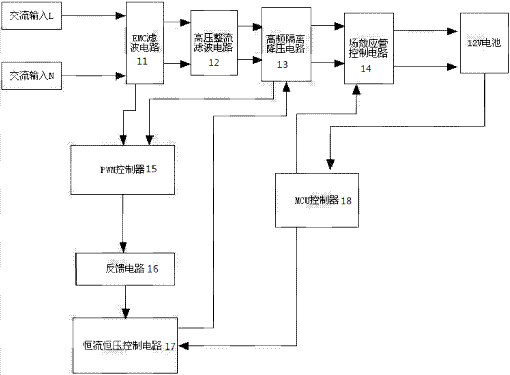
[0031] Such as figure 1 As shown, the present invention provides a charger, and the charger includes: an AC power input terminal, an EMC filter circuit 11, a high-voltage rectification filter circuit 12, a high-frequency isolation step-down circuit 13, a field effect tube control circuit 14, and a PWM control circuit. Device 15, feedback circuit 16, constant current and constant voltage control circuit 17, MCU controller 18 and charging output terminal.

[0032] EMC filter circuit 11 is electrically connected with high voltage rectification filter circuit 12 and PWM controller 15 respectively; The voltage control circuit 17 is electrically connected; the feedback circuit 16 is electrically connected with the PWM controller 15 and the constant current constant voltage control circuit 17 respectively; the MCU controller 18 is respectively connected with the constant current constant voltage control circuit 17, the field effect tube control circuit 14 and the The charging output...

Embodiment 2

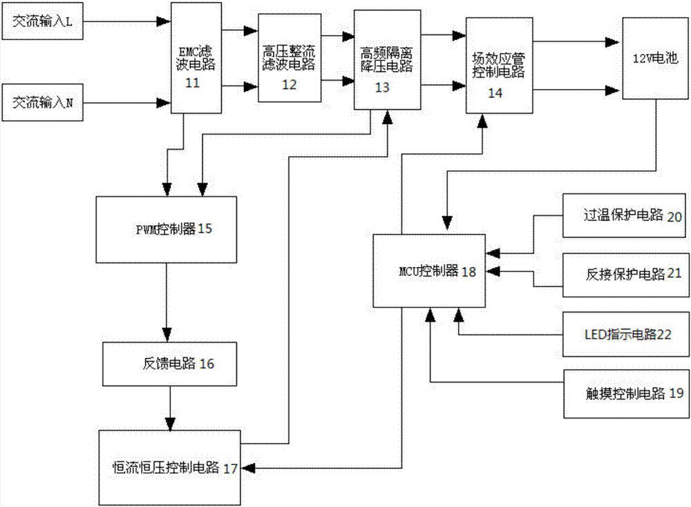
[0040] Such as figure 2 As shown, the present invention provides a charger, and the charger includes: an AC power input terminal, an EMC filter circuit 11, a high-voltage rectification filter circuit 12, a high-frequency isolation step-down circuit 13, a field effect tube control circuit 14, and a PWM control circuit. Device 15, feedback circuit 16, constant current and constant voltage control circuit 17, MCU controller 18, touch control circuit 19, over-temperature protection circuit 20, reverse connection protection circuit 21, LED indicator circuit 22 and charging output terminal.

[0041] EMC filter circuit 11 is electrically connected with high voltage rectification filter circuit 12 and PWM controller 15 respectively; The voltage control circuit 17 is electrically connected; the feedback circuit 16 is electrically connected with the PWM controller 15 and the constant current constant voltage control circuit 17 respectively; the MCU controller 18 is respectively connect...


PUM


Abstract

The invention provides a charger, including: EMC filter circuit, high-voltage rectification and filter circuit, high-frequency isolation step-down circuit, field effect tube control circuit, PWM controller, feedback circuit, constant current and constant voltage control circuit, MCU controller and the charging output terminal; the field effect tube control circuit is used to control whether the charging output terminal is output normally; the PWM controller is used to generate short moment waves to push the power output of the subsequent stage circuit; the constant current and constant voltage control circuit is used to control the said charging output terminal. The charging output terminal outputs constant current or constant voltage; the MCU controller is used to sequentially realize the charging modes of error battery detection, desulfurization, small current pre-charging, constant current charging, constant voltage charging, analysis stage voltage, floating charging, and pulse charging. The charger has multiple charging modes, high charging efficiency, low power loss, and long battery life.

Description

technical field [0001] The invention belongs to the technical field of chargers, and in particular relates to chargers. Background technique [0002] At present, most lead-acid battery chargers on the market use a single constant voltage and current limiting method for charging. Due to the single charging method of the charger, the charging efficiency of the charger is low, the power loss is large, and the service life of the lead-acid battery is also short. Relatively short, how to provide an intelligent charger with multi-stage charging management to meet the needs of high charging efficiency, low power loss, and long battery life is a problem that needs to be solved at present. Contents of the invention [0003] In order to overcome the problems in the prior art, the present invention provides a charger that can provide multi-stage charging management and provide multiple charging modes during the charging process. The charger has high charging efficiency, low power los...

Claims


Application Information

Patent Timeline
Patent Type & Authority Applications(China)
IPC IPC(8): H02J7/04H02J7/00
CPCH02J7/04H02J7/0029H02J7/0047
Inventor 潘少辉
Owner 东莞保力电子有限公司
Why Eureka
Try Eureka