RS triggered interlocking-unlocking circuit

A technology for unlocking circuits and resistors, applied to electrical components, generating electrical pulses, and generating pulses, etc., can solve the problems of complex software judgment, complex circuits, and a large number of relays, and achieve convenient procurement, simple circuit structure, and high circuit reliability. Effect

Active Publication Date: 2017-09-01
BEIJING AEROSPACE PROPULSION INST
View PDF2 Cites 2 Cited by
  • Summary
  • Abstract
  • Description
  • Claims
  • Application Information

AI Technical Summary

Problems solved by technology

Due to the complexity of software judgment, the reliability of this circuit is not as high as that of hardware circuits; the other is a dual-mode switch interlock control circuit applied to aviation liquid cooling systems. This circuit uses relay switches for hardware interlock, but the number of relays is relatively small. Many, the circuit is more complicated

Method used


Image

  • RS triggered interlocking-unlocking circuit

Examples


Embodiment Construction

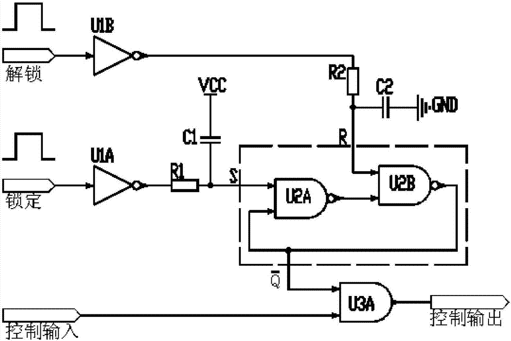
[0020] Such as figure 1 As shown, it is a schematic block diagram of the circuit composition of the present invention, first the circuit connection relationship of the present invention is described in detail:

[0021] The circuit includes: NOT gate U1A, NOT gate U1B, NAND gate U2A, NAND gate U2B, AND gate U3A, capacitor C1, capacitor C2, resistor R1, resistor R2; the input pin of the NOT gate U1A is connected to an external The input locking signal, the output pin of the NOT gate U1A is connected to one end of the capacitor C1 and the input pin of the NAND gate U2A after passing through the resistor R1, and the other end of the capacitor C1 is connected to the positive VCC end of the power supply; the input of the NOT gate U1B The pin is connected to the unlock signal input from the outside, and the output pin of the NOT gate U1B is connected to one end of the capacitor C2 and the input pin of the NAND gate U2B after passing through the resistor R2, and the other end of the c...


PUM


Abstract

The invention discloses a RS triggered interlocking-unlocking circuit. The RS triggered interlocking-unlocking circuit comprises a NOT gate U1A, a NOT gate U1B, a NAND gate U2A, a NAND gate U2B, an AND gate U3A, a capacitor C1, a capacitor C2, a resistor R1, and a resistor R2, wherein the input pin of the NOT gate U1A is connected with a locking signal, the output pin of the NOT gate U1A is respectively connected with one end of the capacitor C1 and the input pin at one end of the NAND gate U2A after passing through the resistor R1, and the other end of the capacitor C1 is connected with a positive VCC end of a power supply; the input pin of the NOT gate U1B is connected with an unlocking signal from the external input, the output pin of the NOT gate U1B is respectively connected with one end of the capacitor C2 and the input pin at one end of the NAND gate U2B after passing through the resistor R2, and the other end of the capacitor C2 is connected with the power supply ground GND end; the output pin of the NAND gate is connected to the input pin at other end of the NAND gate U2B, and the output pin of the NAND gate U2B is respectively connected with the input pin at the other end of the NAND gate U2A and the input end at one end of the AND gate U3A; the input pin at the other end of the AND gate U3A is connected with an initial control signal from the external input, and is capable of producing the processed control signal through the output pin of the AND gate U3A, and then the processed signal is output to the external.

Description

technical field [0001] The invention belongs to the technical field of circuit control and relates to an RS trigger interlock unlocking circuit. Background technique [0002] With the continuous development of circuit control technology, there are more and more applications of interlock circuits. Among them, the interlock circuit is usually used for the control interlock and protection of some special work processes to prevent misoperation or circuit failure, thereby ensuring system safety and personnel safety. Common interlocking measures include software interlocking, hardware circuit interlocking, software and hardware interlocking and so on. [0003] At present, there are usually two types of interlock circuits. One is an interlock circuit that combines software and hardware. The circuit is detected and judged by software, combined with hardware gate circuit interlock to realize control signal output. Due to the complexity of software judgment, the reliability of this ...

Claims


Application Information

Patent Timeline
Patent Type & Authority Applications(China)
IPC IPC(8): H03K3/356
CPCH03K3/356
Inventor 马兵兵张红霞弭艳许海吴岩郑大生王宝艳
Owner BEIJING AEROSPACE PROPULSION INST
Why Eureka
Try Eureka