Spectrum confocal measurement system calibrating device and calibrating method

A measurement system and spectral confocal technology, applied in measurement devices, optical devices, instruments, etc., can solve problems such as difficulty in designing linear dispersive objective lenses, deterioration of linearity of dispersive objective lenses, and difficult dispersive objective lenses, etc. Strict requirements, reduced requirements, and the effect of improving measurement accuracy

Inactive Publication Date: 2017-09-05
ACAD OF OPTO ELECTRONICS CHINESE ACAD OF SCI
View PDF4 Cites 21 Cited by
  • Summary
  • Abstract
  • Description
  • Claims
  • Application Information

AI Technical Summary

Problems solved by technology

However, it is difficult to achieve ideal linear dispersion objective lens in practice. First, it is difficult to design an ideal linear dispersion objective lens in the optical design stage. Secondly, even if a dispersion objective lens with good linearity is designed, due to the dispersion objective lens Inevitable errors in the process of processing, coating, and assembly will also deteriorate the linearity of the dispersion objective lens

Method used


Image

  • Spectrum confocal measurement system calibrating device and calibrating method
  • Spectrum confocal measurement system calibrating device and calibrating method
  • Spectrum confocal measurement system calibrating device and calibrating method

Examples


Embodiment Construction

[0033] Exemplary embodiments of the present invention will be described in more detail below with reference to the accompanying drawings. Although exemplary embodiments of the present invention are shown in the drawings, it should be understood that the invention may be embodied in various forms and should not be limited to the embodiments set forth herein. Rather, these embodiments are provided for more thorough understanding of the present invention and to fully convey the scope of the present invention to those skilled in the art.

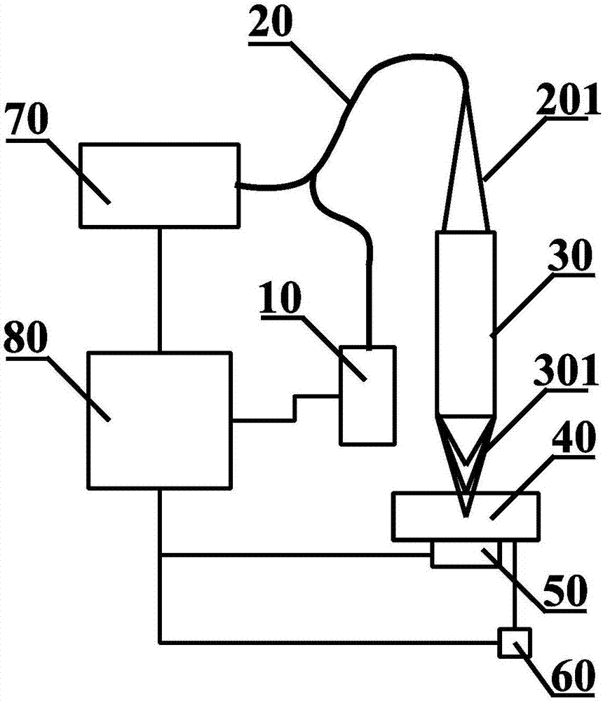
[0034] Such as figure 1 As shown, the schematic diagram of calibration device of spectral confocal measurement system of the present invention, tunable laser (10), double-branch optical fiber (20), optical fiber exit beam (201), dispersion objective lens (30), dispersion objective lens exit beam (301 ), a test object (40), a displacement platform (50), a displacement sensor (60), a spectrometer (70) and a computer (80).

[0035]The laser beam ...


PUM


Abstract

The invention discloses a spectrum confocal measurement system calibrating device and calibrating method. The spectrum confocal measurement system calibrating device comprises a tunable laser, a double-branch optical fiber, an optical fiber emergent light beam, a dispersion object lens, a dispersion object lens emergent light beam, an object to be detected, a displacement table, a spectrometer and a computer. The spectrum confocal measurement system calibrating method comprises steps of recording a position of a detected object, on which a displacement is applied, through a displacement sensor, setting an output wavelength range of the tunable laser to enable the tunable laser to successively emit monochromatic laser beams covering a working waveband of the dispersion object lens, recording the size of the wavelength of the laser beam emitted by the tunable laser in the current lambda and a spectrum signal having a biggest amplitude in the spectrometer and a pixel number n corresponding to a peak value position of the spectrum signal, and establishing a relation between a wavelength and displacement of the detected object through a correspondence relation between the n and the lambda. The spectrum confocal measurement system calibrating device and calibrating method effectively reduce requirements of the dispersion object lens for linearity in the spectrum confocal measurement system and improves measurement accuracy of the spectrum confocal measurement system.

Description

technical field [0001] The invention relates to the technical field of optical measurement, in particular to the calibration of a spectral confocal measurement system. Background technique [0002] The spectral confocal method is a non-contact micro-displacement measurement method based on wavelength displacement modulation. It has the advantages of high measurement accuracy, fast speed, insensitivity to the texture and inclination of the measured surface, and no special requirements for materials. It has important application and development prospects in precision engineering such as manufacturing and ultra-precision manufacturing, micro-machines, micro- and ultra-fine processing. [0003] There are many factors that affect the measurement accuracy of the spectral confocal system, such as the resolution of the spectrometer, the linearity of the dispersive objective lens, etc., usually need to be specially designed and individually calibrated for each factor that affects the...

Claims


Application Information

Patent Timeline
Patent Type & Authority Applications(China)
IPC IPC(8): G01B21/02G01B11/02
CPCG01B11/02G01B21/042
Inventor 卢增雄齐月静王宇刘广义齐威苏佳妮杨光华李兵
Owner ACAD OF OPTO ELECTRONICS CHINESE ACAD OF SCI
Why Eureka
Try Eureka