Finger like slug flow dissipation and separation device

A separation device and slug flow technology, which is applied in the direction of production fluid, wellbore/well components, earthwork drilling and production, etc., can solve problems such as ineffective treatment of slug flow, large pressure loss of multiphase flow, and unstable separation process , to achieve good impact resistance, ensure safe development, and low cost

Inactive Publication Date: 2017-09-08
CHINA UNIV OF PETROLEUM (EAST CHINA)
View PDF8 Cites 7 Cited by
  • Summary
  • Abstract
  • Description
  • Claims
  • Application Information

AI Technical Summary

Problems solved by technology

[0004] Chinese patent 200680008192.4 (authorized patent announcement number CN 101160448 A) discloses a pipe separator inlet device, the inlet device has a plurality of vertical upward degassing pipes, and terminates in an upwardly inclined gas collection pipe, the end of the inlet device is The delivery pipe with enlarged diameter and downward slope makes the gas phase collect into the gas collecting pipe and the liquid phase remains in the delivery pipe; this patent is only a single separator inlet device, and there is no structural component for efficient treatment of slug flow, and the treatment limited quantity
Chinese patent 200680015023.3 (authorized patent announcement number CN 101171401 A) discloses a tubular separator, which uses a slightly inclined large-diameter, long-length curved tubular structure for multiphase flow separation; this patent mainly relies on The residence time is used for separation, the function is single and the structure is not compact enough
Chinese patent 201420080288.3 (authorized patent announcement number CN203796250 U) discloses a deep sea underwater multi-pipe horizontal gas-liquid separator, which arranges multiple groups of single pipes in parallel on the inlet pipe, and each single pipe is respectively equipped with A deflector, where the multiphase flow is swirled and separated due to the density difference; in this patent, the pressure loss of the multiphase flow is large, and the incoming flow received by each single pipe is not equal, and the overall separation process is unstable

Method used


Image

  • Finger like slug flow dissipation and separation device
  • Finger like slug flow dissipation and separation device
  • Finger like slug flow dissipation and separation device

Examples


Embodiment Construction

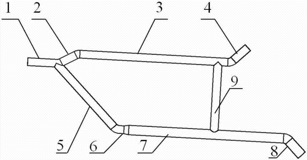
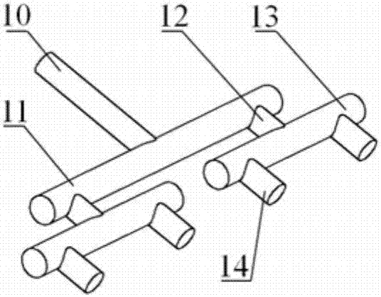
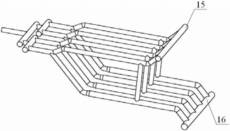
[0023] See attached figure 1 , 2 , 3, a finger-shaped slug flow dissipation separation device is characterized in that it includes an inlet shunt pipe, a finger branch pipe, a gas collection manifold and a liquid collection manifold, including: a finger-shaped inlet pipe 1, an updipping pipe 2, Gas phase jacking pipe 3, upward inclined gas phase outlet pipe 4, downward inclined pipe 5, diameter expansion pipe 6, liquid phase bottom pipe 7, downward inclined liquid phase outlet pipe 8, standpipe 9, diversion inlet pipe 10, primary diversion manifold 11. Primary diversion outlet pipe 12, secondary diversion manifold 13, secondary diversion outlet pipe 14, gas collection manifold 15, liquid collection manifold 16, etc.

[0024] as attached figure 1 As shown, the finger-shaped inlet pipe 1 is connected with the up-dip pipe 2 and the down-dip pipe 5 to form a Y-shaped pipe structure. Since the down-dip pipe 5 is downward and the up-dip pipe 2 is upward, the two-phase flow enterin...


PUM


Abstract

The invention discloses a finger like slug flow dissipation and separation device. The device mainly comprises an inlet dividing pipe, finger like branch pipes, a gas collecting confluence pipe and a liquid collecting confluence pipe. In the inlet dividing pipe, a liquid slug is evenly divided into multiple streams of two-phase flow which flow downstream, and the speed and the momentum are reduced; one part of the two-phase flow which flows into the finger like branch pipes directly flows into a gas-phase jacking pipe, so that the work load of a declination pipe is relieved, and the other part of the two-phase flow flows into the declination pipe and layered dissipation is completed; in a liquid-phase bottom pipe with the diameter expanded, the flow velocity of the two-phase flow further decreases; in a standing pipe, a space exchange is conducted between the liquid phase of the gas-phase jacking pipe and the gas phase of the liquid-phase bottom pipe; finally, both the gas phase and the liquid phase after separation are conveyed downstream in a single-phase flow state through the gas collecting confluence pipe and the liquid collecting confluence pipe respectively. According to the device, the pipe structure is compact, the separation efficiency is high, the pressure bearing capacity is high, impact resistance is high, and the cost is low, so that it is ensured that a deepwater gas field is safely employed and the economic benefit is improved.

Description

technical field [0001] The invention relates to a finger-shaped slug flow dissipation separation device, which is used for separating gas-liquid two-phase flow to facilitate subsequent single-phase pressurized transportation. It adopts a tubular structure with compact structure, high separation efficiency, strong pressure bearing capacity and impact resistance. Strong and low cost, belonging to the technical field of multiphase separation of oil and gas gathering and transportation systems. Background technique [0002] During the development and production of deep-water condensate gas fields, condensate will continue to be generated, and these condensate will accumulate in low-lying places in the pipeline, deteriorating the flow state. At this time, if the multiphase pressurization technology is used to transport the well fluid to the shore, there will be disadvantages such as low pressurization efficiency and poor reliability; at the same time, flow safety such as severe s...

Claims


Application Information

Patent Timeline
Patent Type & Authority Applications(China)
IPC IPC(8): E21B43/36
CPCE21B43/36
Inventor 罗小明耿耿何利民吕宇玲杨东海
Owner CHINA UNIV OF PETROLEUM (EAST CHINA)
Why Eureka
Try Eureka