AI technical title is built by Patsnap AI team. It summarizes the technical point description of the patent document.
An optical scanning and axial positioning technology, which is applied in the direction of the instrument, can solve the problem of low resolution of the scanning axial distance
Inactive Publication Date: 2017-09-08
UNIV OF ELECTRONICS SCI & TECH OF CHINA
View PDF2 Cites 2 Cited by
Summary
Abstract
Description
Claims
Application Information
AI Technical Summary
This helps you quickly interpret patents by identifying the three key elements:
Problems solved by technology
Method used
Benefits of technology
Problems solved by technology
[0007] The technical problem to be solved by the present invention is: to provide an optical scanning holographic axial positioning method based on the TR-MUSIC algorithm, and to solve the problem of low resolution of the scanning axial distance in the prior art optical scanning holographic technology
Method used
Image
Click on the blue label to locate the original text in one second.
Reading with bidirectional positioning of images and text.
Examples
Embodiment 1
[0089] The present invention uses the TR-MUSIC algorithm to realize the axial super-resolution positioning of the object, which has ultra-high precision and resolution, and is now explained through the following simulation research:
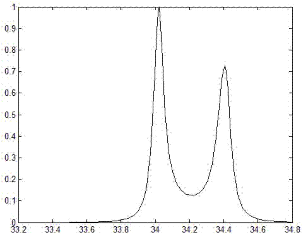
[0090] Simulation 1, z 1 = 34mm, z 2 = 34.4 mm, z 1 and z 2 When a detection target is placed at (10, 5), such as Figure 3a shown.
[0091] Simulation 2, z 1 = 34mm, z 2 = 34.04mm, z 1 and z 2 When a detection target is placed at (10, 5), such as Figure 3b shown.
[0092] Simulation 3, z 1 = 100 μm, z 2 = 100.004 μm, z 1 and z 2 When a detection target is placed at (10, 5), such as Figure 3c shown.
[0093] According to a and b in Figure 3, it can be seen that for an object with an axial distance of 34mm, its resolution can reach 0.4mm, while from Figure 3c It can be seen that the resolution of an object with an axial distance of 100 μm can reach 0.004 μm. Therefore, the method is considered to have high resolution.
[0094]...
Embodiment 2
[0148] The invention uses the TR-MUSIC algorithm to realize the axial super-resolution positioning of the object, is less affected by noise, and has a wide application range. This is illustrated by the following simulation studies:
[0149] Simulation 4, z 1 = 100 μm, z 2 = 100.008 μm, z 1 and z 2 When a detection target is placed at (10, 5) and 60dB Gaussianwhite noise is added, such as Figure 4 As shown, it can be seen that the present invention is less affected by noise.
[0150] The implementation steps of this simulation study are the same as those of the simulation study in Embodiment 1, and will not be repeated here.
Embodiment 3
[0152] The present invention uses the TR-MUSIC algorithm to realize axial super-resolution positioning of an object, and can effectively perform super-resolution axial positioning on multiple points in a single layer. Specifically, the simulation is described as follows:
[0153] Simulation 5, z 1 = Place 4 points at 100μm, z 2 = When 4 points are placed at 101μm, such as Figure 5a shown.
[0154] Simulation 6, z 1 = Place 4 points at 100μm, z 2 = When placing 3 points at 101μm, such as Figure 5b shown.
[0155] Simulation 7, z 1 = Place 4 points at 100μm, z 2 = When 2 points are placed at 101μm, such as Figure 5c shown.
[0156] According to the above simulation, it can be seen that the present invention is still applicable to multi-point objects, and the resolution can reach 1 μm.
[0157] The implementation steps of this simulation study are the same as those of the simulation study in Embodiment 1, and will not be repeated here.
PUM
Abstract
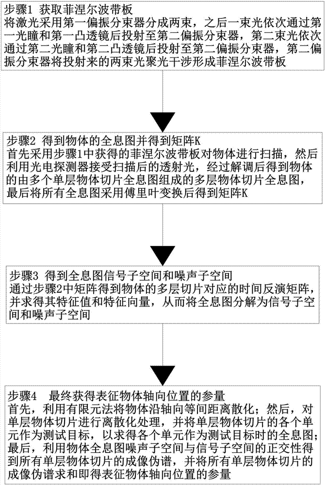
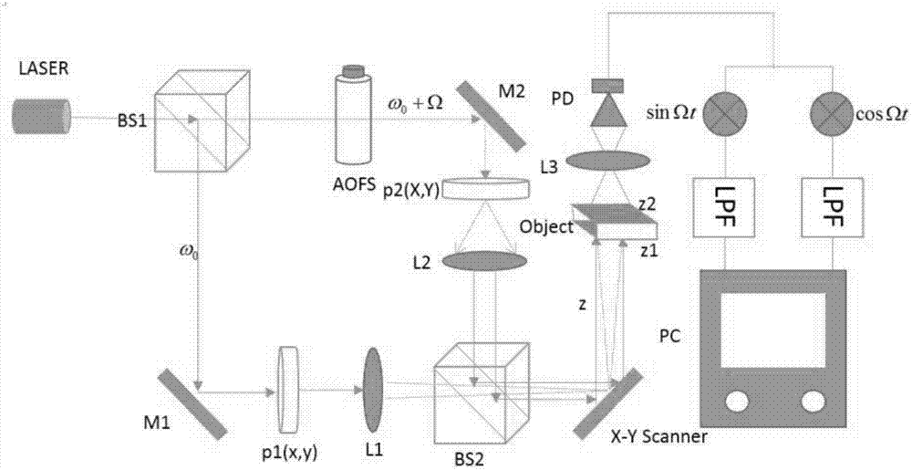
The invention discloses a TR-MUSIC algorithm-based optical scanning holographic axial positioning method, and solves the problem of low scanning axial distance resolution of the optical scanning holographic technology in the prior art. The optical scanning holographic axial positioning method comprises the following steps of forming a Fresnel zone plate by concentrated interference after laserbeam splitting; then scanning an object by the Fresnel zone plate to obtain a hologram of the object, and performing fourier transform on the hologram to obtain a matrix K; next, obtaining a time reversal matrix corresponding to a multilayered slice of the object through the matrix K and then solving a characteristic value and a characteristic vector so as to decompose the hologram into a signal sub space and a noise sub space; and finally performing equal-spacing discretization on the single-layer slice of the object by a finite element method and taking each unit as test targets to solve the hologram, and then obtaining imaging pseudo spectrum of all single-layer object slices, and performing summation on the imaging pseudo spectrum to represent the parameter of the axial position of the object. The optical scanning holographic axial positioning method is simple in realization way, convenient to operate and is quite high in practicability.
Description
technical field [0001] The invention relates to the field of optical scanning holographic technology and spatial positioning, in particular to an optical scanning holographic axial positioning method based on the TR-MUSIC algorithm. Background technique [0002] Optical scanningholography, referred to as OSH, is an important branch of digital holography. It uses optical scanning technology to store the 3D information slice of the object as 2D information, so as to obtain the hologram of the object. This technology was proposed by Poon and Korpel in 1979 when they were studying the acousto-optic heterodyneimage processor. Since the technology was proposed, it has been widely used in the fields of scanning holographic microscope, 3D image recognition and 3D optical remote sensing. [0003] In the field of optical scanning holography technology, since the reconstruction process of hologram needs to use the distance from the scanning mirror to the object, obtaining accurate ...
Claims
Application Information
Patent Timeline
Application Date:The date an application was filed.
Publication Date:The date a patent or application was officially published.
First Publication Date:The earliest publication date of a patent with the same application number.
Issue Date:Publication date of the patent grant document.
PCT Entry Date:The Entry date of PCT National Phase.
Estimated Expiry Date:The statutory expiry date of a patent right according to the Patent Law, and it is the longest term of protection that the patent right can achieve without the termination of the patent right due to other reasons(Term extension factor has been taken into account ).
Invalid Date:Actual expiry date is based on effective date or publication date of legal transaction data of invalid patent.

