
Axial permanent magnet assisted radial reluctance high-speed motor with hybrid cooling structure

A hybrid cooling and high-speed motor technology, applied in the direction of cooling/ventilation device, magnetic circuit shape/style/structure, magnetic circuit, etc., can solve the problem of complex distribution of high-speed motor rotating fluid field, unable to fully take away heat from the motor, and cooling of high-speed motors Poor performance and other problems, to achieve the effect of lowering the maximum temperature, reducing copper consumption, and enhancing heat dissipation

Pending Publication Date: 2017-09-08
SHENYANG POLYTECHNIC UNIV
View PDF6 Cites 28 Cited by
  • Summary
  • Abstract
  • Description
  • Claims
  • Application Information

AI Technical Summary

Problems solved by technology

Due to the limitation of its cooling structure, the existing high-speed motor adopts a self-contained fan cooling method (the rotating shaft drives the fan to blow the cooling air to the heat dissipation ribs on the outer surface of the casing and the end cover, and then the heat inside the motor will be taken away by the heat dissipation ribs). However, this cooling method cannot fully take away the heat generated inside the motor, resulting in poor cooling performance and limited application range of high-speed motors
Moreover, the distribution of the rotating fluid field of a high-speed motor is relatively complex, and the temperature rise of the motor rotor and stator has become a restrictive factor that directly affects the long-term stable operation of the motor.

Method used


Image

  • Axial permanent magnet assisted radial reluctance high-speed motor with hybrid cooling structure
  • Axial permanent magnet assisted radial reluctance high-speed motor with hybrid cooling structure
  • Axial permanent magnet assisted radial reluctance high-speed motor with hybrid cooling structure

Examples


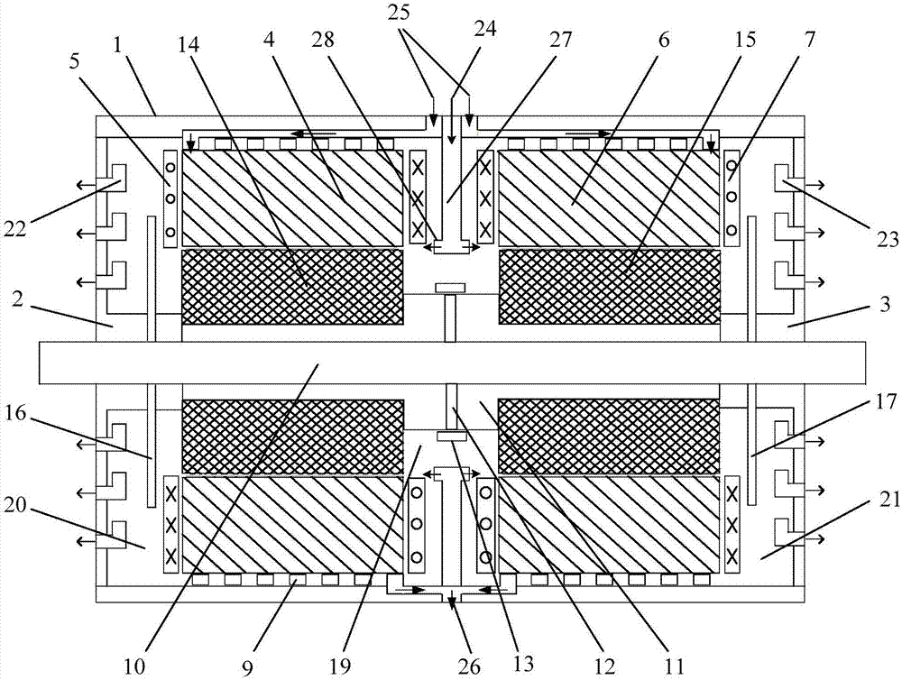
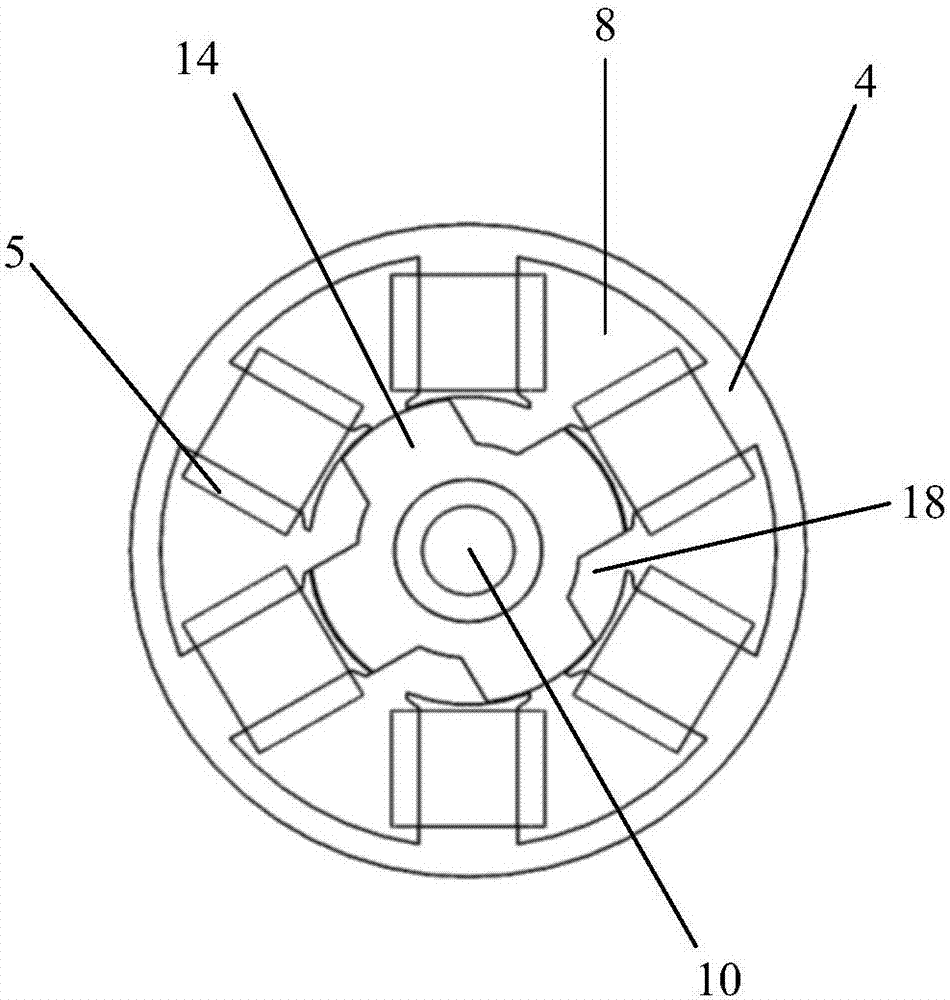
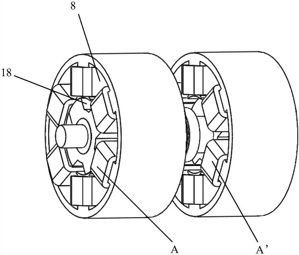
Embodiment Construction

[0028] The specific implementation manners of the present invention will be further described in detail below in conjunction with the accompanying drawings and embodiments. The following examples are used to illustrate the present invention, but are not intended to limit the scope of the present invention.

[0029] An axial permanent magnet assisted radial reluctance high-speed motor with a hybrid cooling structure, such as figure 1 As shown, it includes a casing 1, a front end cover 2, a rear end cover 3, a stator and a rotor. The basic structure of the motor is a double-group 6 / 4-pole switched reluctance motor structure. The structures on both sides of the motor (except for the rotor) are arranged in parallel and completely symmetrical to the middle vertical plane of the motor shaft. Six protrusions are evenly distributed on each side of the stator core. poles, and 4 salient poles are evenly distributed on each side of the rotor core, which is a double-set salient pole stru...


PUM


Abstract

The invention provides an axial permanent magnet assisted radial reluctance high-speed motor with a hybrid cooling structure, and relates to the technical field of motors. The motor provided by the invention is provided with an air cooling and water cooling structure on the basis of a dual group 6 / 4-pole switched reluctance motor structure. The motor comprises a casing, a front end cover, a rear end cover, a rotor and a stator, and is characterized in that an inter-tooth slot of the stator and the rotor form a cooling air channel, each end cover is provided with air discharging holes, the casing is provided with a cooling air inlet, a cooling water inlet pipe opening, a cooling water outlet pipe opening and a circumferential ring-shaped air guiding channel, the back of a ring yoke of the stator is provided with a spiral water channel pipe, and two ends of the rotor are provided with self-cooling fans respectively. According to the invention, a cooling structure combining the air cooling stator and the water cooling stator is adopted, and a water cooling function and an air cooling function are opposite in direction and complementary in cooling region, so that the stator and the rotor of the motor are effectively enabled to be reduced in temperature, a problem of difficult heat dissipation of the motor under a high-speed operating condition is avoided, thus long-term safe and stable running of the motor is ensured, and the service life of the motor is effectively prolonged.

Description

technical field [0001] The invention relates to the technical field of motors, in particular to an axial permanent magnet assisted radial reluctance high-speed motor with a hybrid cooling structure. Background technique [0002] At present, new high-speed motors have become an important development direction of high-efficiency and energy-saving motors. Due to the limitation of its cooling structure, the existing high-speed motor adopts a self-contained fan cooling method (the rotating shaft drives the fan to blow the cooling air to the heat dissipation ribs on the outer surface of the casing and the end cover, and then the heat inside the motor will be taken away by the heat dissipation ribs). However, this cooling method cannot sufficiently remove the heat generated inside the motor, resulting in poor cooling performance and limited application range of high-speed motors. Moreover, the distribution of the rotating fluid field of a high-speed motor is relatively complex, an...

Claims


Application Information

Patent Timeline
Patent Type & Authority Applications(China)
IPC IPC(8): H02K16/00H02K1/14H02K1/20H02K9/197H02K1/32H02K9/06H02K5/20H02K1/27
CPCH02K1/14H02K1/20H02K1/2706H02K1/32H02K5/20H02K9/06H02K9/197H02K16/00H02K2213/03
Inventor 刘爱民任达娄家川孙鹏高智超李家尧李博韦有帅
Owner SHENYANG POLYTECHNIC UNIV
Learn More