Microwave oven magnetron power supply device with pull-up active clamping branch

A technology of power supply device and magnetron, which is applied in the field of electricity, can solve the problems of burnout of the upper and lower switch tubes of the bridge arm, high power supply cost, and increased loss, and achieve the effect of constant power control

Active Publication Date: 2017-09-08
QINGDAO UNIV
View PDF5 Cites 5 Cited by
  • Summary
  • Abstract
  • Description
  • Claims
  • Application Information

AI Technical Summary

Problems solved by technology

[0004] At present, the magnetron power supply circuit of household frequency conversion microwave oven generally adopts LLC resonant half-bridge inverter circuit topology or LC resonant single-tube bipolar inverter circuit topology. The switch tube is easy to cause straight-through and burnout problems; although the latter has the advantages of simple circuit structure, low cost, high efficiency, and zero-voltage turn-on and zero-voltage turn-off control, it also has some disadvantages. When the input voltage of the microwave oven is 220V ac / 50Hz alternating current, the switching tube of the microwave oven is subjected to a withstand voltage as high as 1200V or more during operation, so that the switching tube can only use an insulated gate field effect transistor (IGBT) with a higher withstand voltage, and in order to linearly adjust the output power of the magnetron, The switching frequency of the IGBT single tube needs to be modulated by frequency conversion from 20kHz to 40kHz. When the switching frequency of the IGBT is greater than 25kHz, its loss will increase with the increase of the switching frequency, which restricts the further improvement of the switching frequency. The volume and cost of the power supply device are further reduced, which is not conducive to the popularization and application of this new type of microwave oven magnetron power supply

Method used


Image

  • Microwave oven magnetron power supply device with pull-up active clamping branch
  • Microwave oven magnetron power supply device with pull-up active clamping branch
  • Microwave oven magnetron power supply device with pull-up active clamping branch

Examples


Embodiment

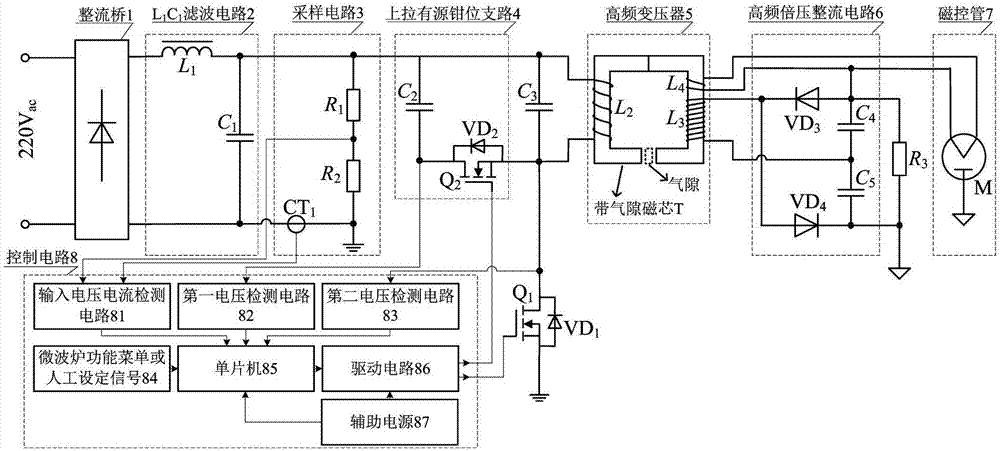
[0020] The main structure of the microwave oven magnetron power supply device with a pull-up active clamping branch described in this embodiment includes a rectifier bridge 1, L 1 C 1Filter circuit 2, sampling circuit 3, pull-up active clamping branch 4, resonant capacitor C 3 , main switching tube Q 1 , the first diode VD 1 , High-frequency transformer 5, High-frequency voltage doubler rectifier circuit 6, Discharge resistor R 3 , magnetron 7 and control circuit 8, the first diode VD 1 main switch Q 1 Anti-parallel diodes, single-phase power frequency alternating current through the rectifier bridge 1, L 1 C 1 After filter circuit 2, it is converted into direct current, and the main switching tube Q 1 , the first diode VD 1 and the pull-up active clamping branch 4 to invert the direct current into high-frequency alternating current, and this high-frequency alternating current is applied to the primary winding L of the high-frequency transformer 5 2 Both ends, after b...


PUM


Abstract

The invention belongs to the technical field of electricity and relates to a microwave oven magnetron power supply device with a pull-up active clamping branch. The pull-up active clamping branch is additionally arranged in an LC resonant single-tube bipolar inversion circuit topology for a variable-frequency microwave oven magnetron power supply, the branch comprises an auxiliary switch tube, the switching frequencies of a main switch tube and the auxiliary switch tube are same, soft switch control can be achieved, no problem of direct connection between the two tubes exists, and the reliability is improved; moreover, under the condition of maintaining the advantage of an original circuit, the pressure resistance of the switch tube is reduced to second thirds of the original circuit, the power supply device can employ a metal oxide transistor as the switch tube, and the switching frequency can reach 100kHz or above; and meanwhile, the auxiliary switch tube is short in conduction time and low in power consumption, and thus, a technical scheme is provided for reducing the volume and the weight of a power supply and reducing the cost of the power supply.

Description

[0001] Technical field: [0002] The invention belongs to the field of electrical technology, and relates to a microwave oven magnetron power supply device with an active clamp circuit, in particular to a microwave oven magnetron power supply device with a pull-up active clamp branch circuit. [0003] Background technique: [0004] At present, the magnetron power supply circuit of household frequency conversion microwave oven generally adopts LLC resonant half-bridge inverter circuit topology or LC resonant single-tube bipolar inverter circuit topology. The switch tube is easy to cause straight-through and burnout problems; although the latter has the advantages of simple circuit structure, low cost, high efficiency, and zero-voltage turn-on and zero-voltage turn-off control, it also has some disadvantages. When the input voltage of the microwave oven is 220V ac / 50Hz alternating current, the switching tube of the microwave oven is subjected to a withstand voltage as high as 1...

Claims


Application Information

Patent Timeline
Patent Type & Authority Applications(China)
IPC IPC(8): H02M3/335H02M7/537H02M5/12H02M7/10H02M1/38H05B6/06
CPCH02M1/38H02M3/33569H02M5/12H02M7/103H02M7/537H05B6/06H02M1/0009H02M1/0038H02M1/0058Y02B70/10
Inventor 王春芳李震魏芝浩
Owner QINGDAO UNIV
Why Eureka
Try Eureka