
Plastic garbage treatment neutralizing device

A plastic waste pretreatment technology, applied in fertilization equipment, transportation and packaging, sustainable waste treatment, etc., can solve problems such as long time period, equipment not working, and environmental secondary pollution

Inactive Publication Date: 2017-09-12
HENAN DIZHILV ENVIRONMENTAL PROTECTION TECH CO LTD
View PDF0 Cites 1 Cited by
  • Summary
  • Abstract
  • Description
  • Claims
  • Application Information

AI Technical Summary

Problems solved by technology

[0002] Plastic waste is one of the common wastes in daily production and life. Due to the difficulty of degradability of plastic waste, the current methods of dealing with plastic waste mainly use landfill, burning, and cracking; the landfill method is to buy plastic waste into the ground, By its natural degradation, this method takes a long time, has a great impact on the environment, and occupies land; the burning method is to burn plastic waste, or burn it together with other waste or materials as power generation or other heat sources. After burning, a large amount of toxic gas will be produced, which will cause secondary pollution to the environment; the cracking method is to put plastic waste into the cracking furnace, decompose the plastic again, and produce petroleum substances after decomposition, which can be reused as fuel or other raw materials; In the existing pyrolysis treatment method, there are the following problems. First, the existing complete continuous pyrolysis equipment has requirements for the composition of the plastic in the plastic waste, that is to say, the consistency of the plastic species in the plastic waste is required to be good. The proportion of plastic components needs to reach more than 85%, which can be achieved for countries or regions that do a good job in waste classification, but it is difficult for countries or regions that do not do a good job in waste classification or do not do it meticulously; if not If such composition requirements can be met, the existing pyrolysis equipment cannot realize the pyrolysis of plastic waste, and the equipment will not work at least, and the equipment will explode at worst; moreover, for the treatment method of discontinuous pyrolysis, a large amount of waste will be generated during the pyrolysis process. Toxic gases will still be discharged into the atmosphere, causing secondary pollution to the environment. At the same time, these toxic gases will produce strong acids when they meet water, which will cause serious corrosion of equipment and shorten the service life of equipment; third, due to the presence of different plastic components in cracking, cracking The temperature can only adapt to the pyrolysis temperature of a certain type of plastic, and it is impossible to crack the plastic waste in one pyrolysis furnace. At the same time, it is necessary to sort the plastic types, and the residue after pyrolysis is easy to stick to the furnace wall, causing damage to the cracking furnace. At the same time, cleaning the residue on the furnace wall will also cause secondary pollution to the environment; fourth, the existing plastic waste is sorted by crushing the plastic waste, which consumes a lot of energy and causes energy waste

Method used

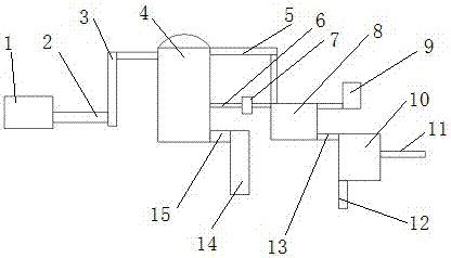

Image

  • Plastic garbage treatment neutralizing device
  • Plastic garbage treatment neutralizing device
  • Plastic garbage treatment neutralizing device

Examples


Embodiment Construction

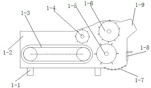
[0042] In order to further illustrate the technical solution of the present invention, the specific implementation manner of the present invention is now described in conjunction with the accompanying drawings, as Figure 1-8 , in this example, a common rack in this industry is selected as the rack 1-1, and the rack 1-1 is installed on the equipment foundation to support and install the entire functional components; the shell 1-1 is made of a steel plate with a thickness of 1 mm 2. Install the shell 1-2 on the frame 1-1; choose the chain conveyor belt commonly used in this industry as the conveyor belt 1-3, install the conveyor belt 1-3 on one end of the frame 1-1, and connect it with the The power and control system are connected, and the plastic waste to be processed can be sent from the feed port of the sorting equipment to the 1-4 of the material; in this example, a hollow cylinder is selected as the main body of the 1-4 of the material, and the two ends Rotating shaft is ...


PUM


Abstract

A plastic garbage treatment neutralizing device is applied to a plastic garbage treatment system and comprises a smoke inlet pipe, a housing, a smoke hood, an exhausting pipe, a spraying device and a chemical fertilizer stock solution outlet. The smoke inlet pipe is mounted at the lower end of the housing; the housing is mounted at the upper end of a combustion chamber, is located on the upper portion of a cracking furnace and is an enclosed cavity; the smoke hood is mounted at the upper end of the smoke inlet pipe; a gap is reserved between the smoke hood and the inner wall of the housing; a gap is reserved between the lower portion of the smoke hood and the upper end of the smoke inlet pipe; the exhausting pipe is arranged on the upper portion of the housing; the spraying device is mounted in the exhausting pipe, is located above the smoke hood, is spaced from the smoke hood by a certain distance and can spray neutralizing liquid to the space formed between the smoke hood and the exhausting pipe; and the chemical fertilizer stock solution outlet is formed in the lower portion of the housing and communicates with an inner cavity of the housing. The plastic garbage treatment neutralizing device has the characteristics that the function of neutralizing harmful gas of the plastic garbage treatment system is achieved, environmental pollution is reduced, and liquid chemical fertilizer products are additionally provided.

Description

technical field [0001] The invention belongs to the field of waste treatment, in particular to a neutralization device in a plastic waste treatment system in a method for continuously treating and comprehensively utilizing plastic waste. Background technique [0002] Plastic waste is one of the common wastes in daily production and life. Due to the difficulty of degradability of plastic waste, the current methods of dealing with plastic waste mainly use landfill, burning, and cracking; the landfill method is to buy plastic waste into the ground, By its natural degradation, this method takes a long time, has a great impact on the environment, and occupies land; the burning method is to burn plastic waste, or burn it together with other waste or materials as power generation or other heat sources. After burning, a large amount of toxic gas will be produced, which will cause secondary pollution to the environment; the cracking method is to put plastic waste into the cracking fu...

Claims


Application Information

Patent Timeline
Patent Type & Authority Applications(China)
IPC IPC(8): B09B3/00B09B5/00C04B18/04C05C3/00
CPCC04B18/0427C05C3/00B09B3/00B09B5/00B09B3/40Y02W30/91
Inventor 张振堂余华龙
Owner HENAN DIZHILV ENVIRONMENTAL PROTECTION TECH CO LTD
Learn More