Laser processing machine

A laser processing machine and laser processing head technology, applied in laser welding equipment, metal processing equipment, manufacturing tools, etc., can solve the problems of expensive, material-intensive manufacturing, etc., to reduce the impact of damage, simplify the structure, and reduce the risk of damage Effect

Pending Publication Date: 2017-09-12
BYSTRONIC LASER
View PDF13 Cites 3 Cited by
  • Summary
  • Abstract
  • Description
  • Claims
  • Application Information

AI Technical Summary

Problems solved by technology

[0008] The disadvantage of the known solutions is that the construction of the laser processing machine and in particular the dust collection space is material intensive and expensive to manufacture

Method used


Image

  • Laser processing machine
  • Laser processing machine
  • Laser processing machine

Examples


Embodiment Construction

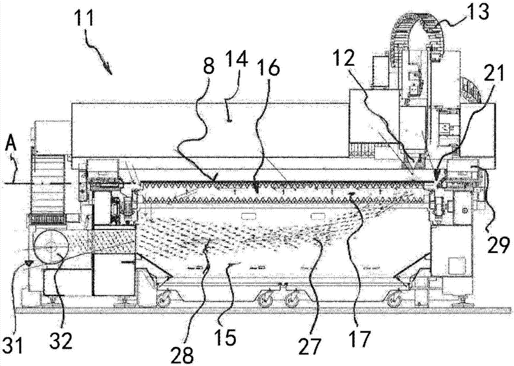
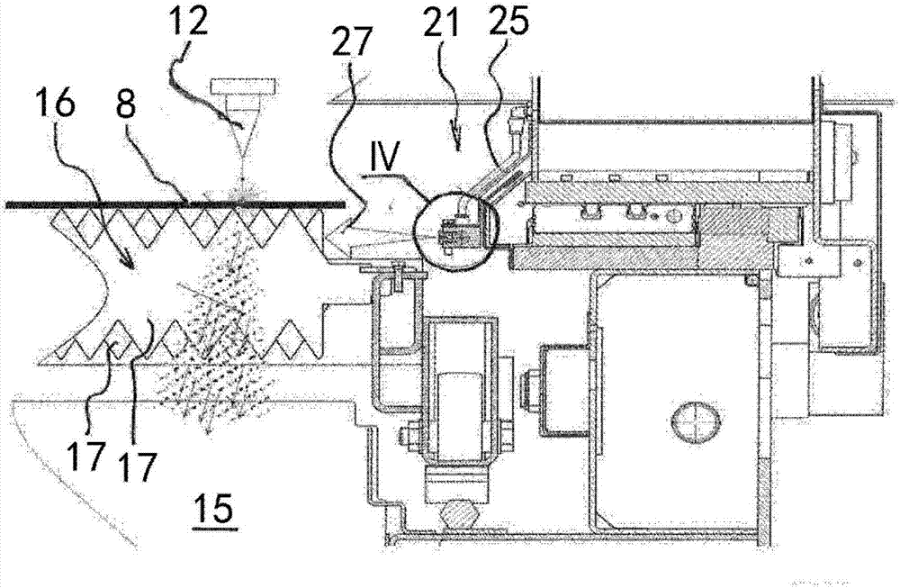
[0076] Figure 1 to Figure 3 The laser processing machine 11 shown is a laser cutting machine with a laser cutting head 12 as a laser processing head. The laser processing machine 11 also includes a dust collection space 15 covered by a support grid 16 . The support grid 16 defines a support plane A for supporting the workpiece 8 to be machined. The support grid 16 comprises a plurality of grid elements 17 parallel to each other and spaced apart from each other.

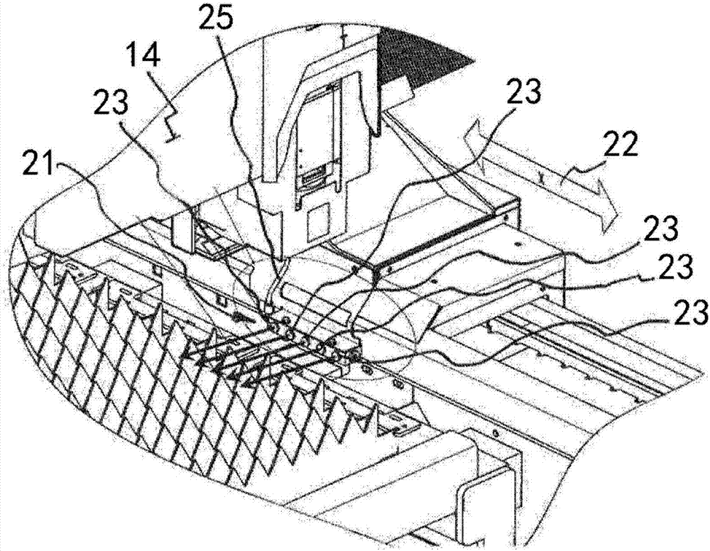
[0077] The laser cutting head 12 is arranged on a bridge 14 . In order to position the laser cutting head 12 relative to the workpiece 8 , the workpiece 8 can be moved along the bridge 14 and with this bridge 14 in the direction of movement of the laser cutting head 12 (double arrow). Energy is supplied to the laser cutting head 12 through a flexible feeder 13 (also referred to as a supply chain).

[0078] Also provided are fluid supply means 21 and fluid removal means 31, which are designed to create, below the ...


PUM


Abstract

The invention relates o a laser processing machine (11) with a laser processing head (12), with a support grate (16) that defines a support plane (A) for supporting a workpiece (8) to be processed, with a fluid supply device (21) and with a fluid removal device (31). The fluid supply device (21) and fluid removal device (31) are designed to generate a fluid flow (27) under the support plane (A) of the support grate (16). The fluid supply device (21) can be moved with the laser processing head (12).

Description

technical field [0001] The invention relates to a laser processing machine according to the preamble of claim 1 . Background technique [0002] During laser processing, especially during laser cutting, exhaust gases and residues such as molten workpiece material or dust deposited on the bottom of the workpiece accumulate in the dust collection space of the laser processing machine. Machined workpieces, such as sheet metal, may become soiled requiring mechanical cleaning prior to subsequent painting since the paint would otherwise not adhere to the workpiece. [0003] Known for removing dust and exhaust gas accumulated in a dust collection space are laser processing machines in which an electric current is generated. [0004] For example, DE 10 2011 050 749 A1 shows a laser processing machine with a suction device that sucks up residues that accumulate on the side of the workpiece facing the laser processing head. [0005] A disadvantage of the known solution is that only a...

Claims


Application Information

Patent Timeline
Patent Type & Authority Applications(China)
IPC IPC(8): B23K26/142B23K26/38
CPCB23K26/142B23K26/38B08B15/00B23K26/16B08B5/02B08B15/04B23K26/1488
Inventor 海因茨·欧伯霍尔泽马提亚斯·维特里奇
Owner BYSTRONIC LASER
Why Eureka
Try Eureka