Photodiode preparation method and photodiode

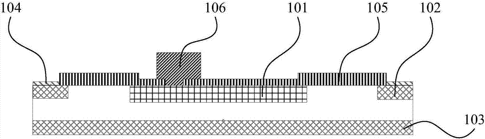
A photodiode and metal electrode technology, applied in circuits, electrical components, semiconductor devices, etc., can solve problems such as light transmission characteristics, lattice defects, and ion damage affecting the oxide layer light transmission window 105 of the photodiode

Active Publication Date: 2017-09-12
FOUNDER MICROELECTRONICS INT
View PDF4 Cites 1 Cited by
  • Summary
  • Abstract
  • Description
  • Claims
  • Application Information

AI Technical Summary

Problems solved by technology

[0003] like figure 1 As shown, the photodiode includes: a first ion-doped region 101, a voltage divider ring 102, a second ion-doped region 103, an oxide layer 104 (that is, an oxide isolation layer), an oxide layer light-transmitting window 105, and a metal electrode 106, Among them, if the metal layer is etched by a dry method, ion damage will be caused to t

Method used


Image

  • Photodiode preparation method and photodiode
  • Photodiode preparation method and photodiode
  • Photodiode preparation method and photodiode

Examples


Embodiment Construction

[0032] In order to understand the above-mentioned purpose, features and advantages of the present invention more clearly, the present invention will be further described in detail below in conjunction with the accompanying drawings and specific embodiments. It should be noted that, in the case of no conflict, the embodiments of the present application and the features in the embodiments can be combined with each other.

[0033] In the following description, many specific details are set forth in order to fully understand the present invention. However, the present invention can also be implemented by a third party different from the third party described here. Therefore, the protection scope of the present invention is not limited by the following disclosure. limitations of specific examples.

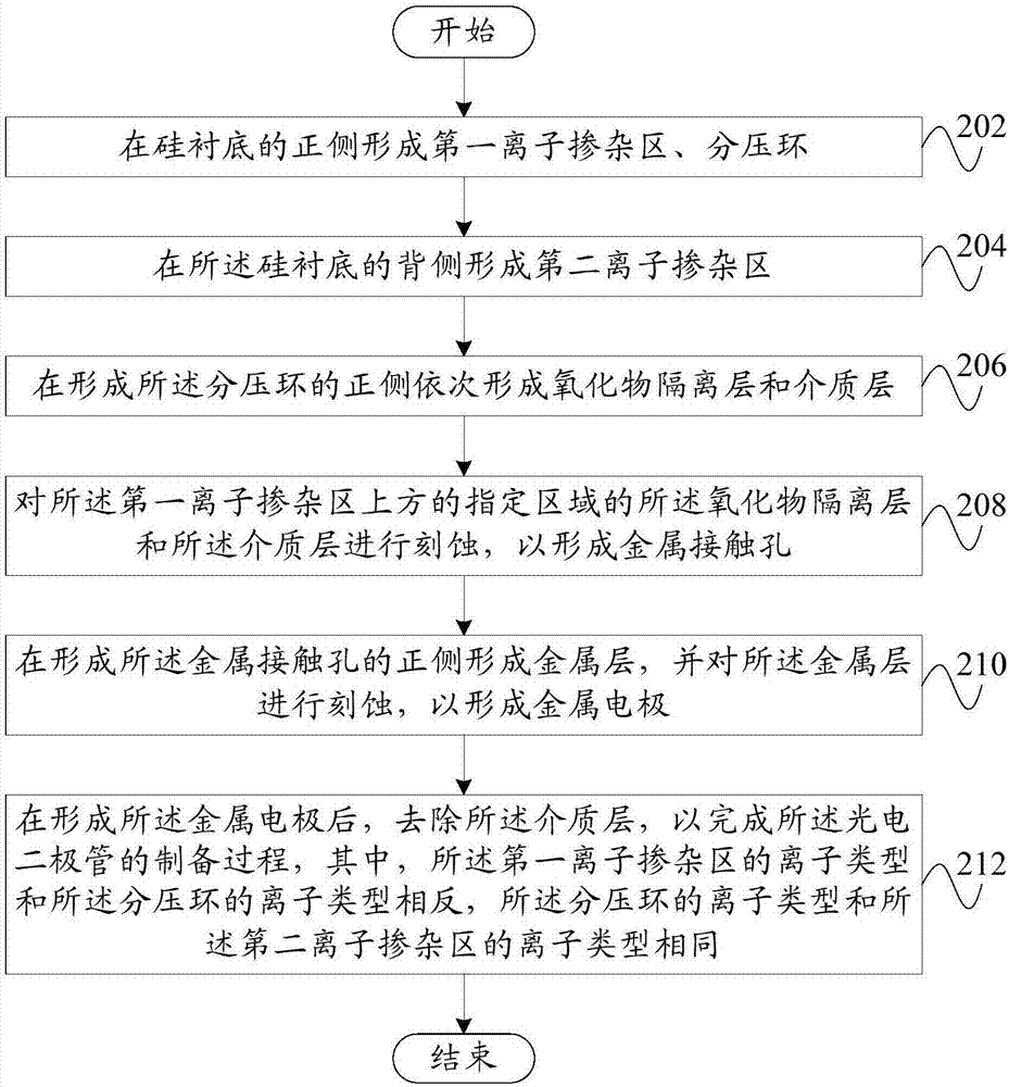
[0034] Combine below Figure 2 to Figure 11 A method of manufacturing a photodiode according to an embodiment of the present invention will be specifically described.

[0035] like ...


PUM


Abstract

The invention provides a photodiode preparation method and a photodiode. The preparation method comprises steps of forming a first ion doping region and a voltage dividing ring on the positive side of a silicon substrate; forming a second ion doping region at the back side of the silicon substrate; forming an oxide isolation layer and a dielectric layer on the positive side of the voltage dividing ring; etching the oxide isolation layer and the dielectric layer in a designated area above the first ion doping region to form a metal contact hole; forming a metal layer on the positive side of the metal contact hole and etching the metal layer to form a metal electrode; and after forming the metal electrode, removing the dielectric layer to complete the preparation process of the photodiode. With the technical scheme of the invention, the metal etching process reduces the pollution and ion damage to the oxide isolation layer, and the device reliability of the photodiode is improved.

Description

technical field [0001] The invention relates to the technical field of semiconductor chips, in particular to a method for preparing a photodiode and a photodiode. Background technique [0002] In the related art, during the fabrication process of the photodiode, before the contact hole is etched to form the metal connection, the ion-doped region of the photodiode is only covered with an oxide layer as an etching mask layer. [0003] like figure 1 As shown, the photodiode includes: a first ion-doped region 101, a voltage divider ring 102, a second ion-doped region 103, an oxide layer 104 (that is, an oxide isolation layer), an oxide layer light-transmitting window 105, and a metal electrode 106, Among them, if the metal layer is etched by a dry method, ion damage will be caused to the oxide layer 104 and the light-transmitting window 105 of the oxide layer, which may cause lattice defects; if the metal layer is etched by a wet method, the oxide layer will be transparent to l...

Claims


Application Information

Patent Timeline
IPC IPC(8): H01L31/18
CPCH01L31/18
Inventor 马万里高振杰石金成
Owner FOUNDER MICROELECTRONICS INT
Why Eureka
Try Eureka