Chip removal device for carving machine

A chip removal device and engraving machine technology, applied in the field of engraving machine machinery, can solve the problems of working environment pollution, scattered under the equipment, incomplete chip removal and cleaning, etc., to reduce environmental pollution, avoid iron filings accumulation, and ensure physical and mental health. Effect

Active Publication Date: 2017-09-15
安徽联合智能装备有限责任公司
View PDF5 Cites 15 Cited by
  • Summary
  • Abstract
  • Description
  • Claims
  • Application Information

AI Technical Summary

Problems solved by technology

The engraving machine is one of the core equipment for the rapid development of modern industry, and it is widely used. The waste cleaning method of the existing engraving machine is generally directly transported from the cutting chamber of the machine tool by the conveyor belt, which will generate a lot of fine chips and dust, which will affect Product quality and equipment life have a great impact on the operator's body and the environment; when engraving metal materials, metal debris will be generated, and the metal debris and cutting fluid will be collected in the chip discharge groove first. The metal chips are gradually pushed out by the chip pushing mechanism. In actual use, a lot of heavy waste chips will be cut off from the metal substrate. These waste chips cannot be drawn out by the ventilation device. During the machining process, they are often accompanied by the The vibration of the vibration is scattered to the bottom of the equipment, which is easy to cause pollution to the working environment, and the metal debris cannot be effectively separated from the cutting fluid, and the chip removal and cleaning are not thorough, which increases the work intensity of the laborers and the production cost.

Method used


Image

  • Chip removal device for carving machine
  • Chip removal device for carving machine
  • Chip removal device for carving machine

Examples


Embodiment Construction

[0018] In order to make the object, technical solution and advantages of the present invention clearer, the present invention will be further described in detail below in conjunction with the accompanying drawings and embodiments. It should be understood that the specific embodiments described here are only used to explain the present invention, not to limit the present invention.

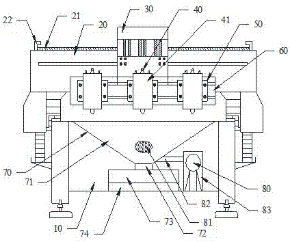
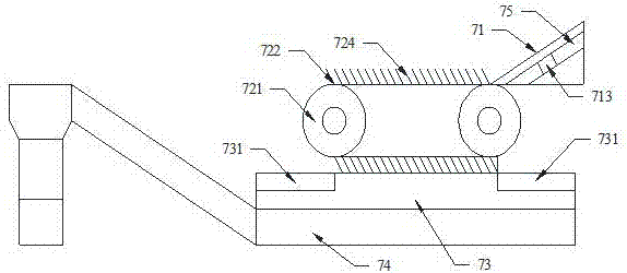
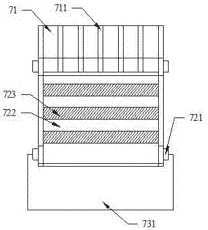
[0019] Such as figure 1 As shown, the present invention provides an assembly diagram of a chip removal device for an engraving machine, such as figure 2 As shown, a schematic structural diagram of a chip removal device for an engraving machine in the present invention includes a bed body 10, a gantry frame 20, a driving device 30, a spindle device 40, and a chip removal device 70. The bed body 10 is provided with a cross-bed The gantry 20 on the two sides of the body 10, the gantry 20 is provided with a driving device 30, a crossbeam 60 and a main shaft device 40 are provided below the driving de...


PUM


Abstract

The invention discloses a chip removal device for a carving machine. The chip removal device comprises a bed body and a chip cleaner. A portal frame crossing the two edges of the bed body is arranged on the bed body, the chip cleaner comprises a sloping baffle, the sloping baffle is located below the working surface of the bed body, and a scrap transmission mechanism is arranged below the sloping baffle; a scrap collecting chamber is arranged below the scrap transmission mechanism, a material-conveying belt is arranged on the bottom surface of the scrap collecting chamber, and an oscillation starting machine is installed on the lower end surface of the sloping baffle; and the scrap transmission mechanism comprises a rotating shaft and a conveyer belt, a scraping plate is installed on the conveyer belt, and a hair brush is installed at the end of the scraping plate. According to the chip removal device for the carving machine, cutting fluid, metal scraps, fines and dust and the like can be effectively separated, iron scraps are prevented from accumulating, and recycling is achieved; and environmental pollution is reduced, and a clean, tidy and healthful working environment is provided for workers.

Description

technical field [0001] The invention relates to the technical field of engraving machine machinery, in particular to a chip removal device for an engraving machine. Background technique [0002] Engraving machine is a commonly used engraving equipment, used to engrave various sculptures and models. With people's understanding and mastery of engraving machines, the application scope and application level will gradually increase, such as advertising industry, seal industry, craft gift industry, art model industry, wood processing industry, mold industry and so on. Machinable materials include acrylic, two-color board, PVC, ABS board, stone, imitation stone, metal, aluminum-plastic board and other materials. The application of engraving machines in the advertising industry is mainly: engraving and cutting various types of signs, coordinate signs, marble, copper, fonts, fonts, various signs, trademarks and other metal materials. The engraving machine is one of the core equipme...

Claims


Application Information

Patent Timeline
Patent Type & Authority Applications(China)
IPC IPC(8): B44B1/06B44B3/06
CPCB44B1/06B44B3/06B44B2700/12
Inventor 罗群罗亮
Owner 安徽联合智能装备有限责任公司
Why Eureka
Try Eureka