Airtight removing method for harmful gas in drilling fluid

A harmful gas and drilling fluid technology, which is applied in earthwork drilling, wellbore flushing, wellbore/well components, etc., can solve the problems that affect the effect and efficiency of hydrogen sulfide removal, and can not remove hydrogen sulfide well, so as to meet the requirements of The effect of safety and environmental protection, improving safety and reducing the cost of use

Active Publication Date: 2017-09-15
BC P INC CHINA NAT PETROLEUM CORP +1
View PDF7 Cites 9 Cited by
  • Summary
  • Abstract
  • Description
  • Claims
  • Application Information

AI Technical Summary

Problems solved by technology

[0005] In the above-mentioned methods for treating hydrogen sulfide in the prior art, excessive addition of desulfurizer to the drilling fluid will have a certain impact on the performance of the drilling fluid material, and therefore will impose certain restrictions on the amount of desulfurizer added. After limiting the addition of sulfur removal agent, it will affect the removal effect and efficiency of hydrogen sulfide, and the hydrogen sulfide in the drilling fluid cannot be removed well.

Method used


Image

  • Airtight removing method for harmful gas in drilling fluid
  • Airtight removing method for harmful gas in drilling fluid
  • Airtight removing method for harmful gas in drilling fluid

Examples


Embodiment 1

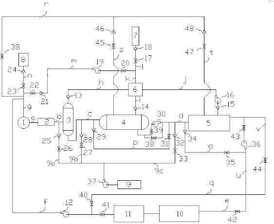
[0028] As a preferred embodiment of the present invention, with reference to the attached figure 1 , this example discloses:

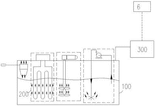
[0029] The method of airtight removal of harmful gas in drilling fluid, the drilling fluid containing harmful gas returns to the ground from the well, and enters the surface drilling fluid airtight treatment system, the drilling fluid containing harmful gas returns from the well, and enters the primary separator after depressurization, The drilling fluid separated by the primary separator is directly introduced into the secondary separator for secondary separation. The working pressure of the secondary separator is lower than that of the primary separator; the drilling fluid separated by the secondary separator is pumped by a centrifugal pump Into the third-level separation system, in the third-level separation system, the participating gases are separated by the combination of negative pressure extraction, submerged turbulence, and fluid temperature c...

Embodiment 2

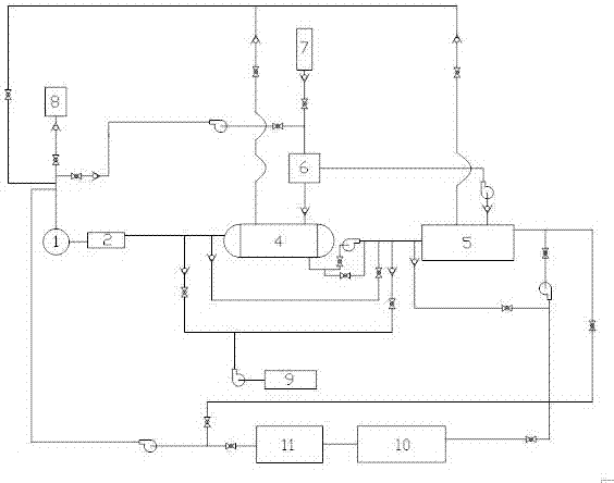
[0031] As another preferred embodiment of the present invention, with reference to the attached figure 1 , this example discloses:

[0032] The method of airtight removal of harmful gas in drilling fluid, the drilling fluid containing harmful gas returns to the ground from the well, and enters the surface drilling fluid airtight treatment system, the drilling fluid containing harmful gas returns from the well, and enters the primary separator after depressurization, The drilling fluid separated by the primary separator is directly introduced into the secondary separator for secondary separation. The working pressure of the secondary separator is lower than that of the primary separator; the drilling fluid separated by the secondary separator is pumped by a centrifugal pump Into the third-level separation system, in the third-level separation system, the participating gases are separated by the combination of negative pressure extraction, submerged turbulence, and fluid tempera...

Embodiment 3

[0038] As another preferred embodiment of the present invention, this embodiment discloses:

[0039] The method of airtight removal of harmful gas in drilling fluid, the drilling fluid containing harmful gas returns to the ground from the well, and enters the surface drilling fluid airtight treatment system, the drilling fluid containing harmful gas returns from the well, and enters the primary separator after depressurization, The drilling fluid separated by the primary separator is directly introduced into the secondary separator for secondary separation. The working pressure of the secondary separator is lower than that of the primary separator; the drilling fluid separated by the secondary separator is pumped by a centrifugal pump Into the third-level separation system, in the third-level separation system, the participating gases are separated by the combination of negative pressure extraction, submerged turbulence, and fluid temperature control; The output gas is introdu...


PUM


Abstract

The invention discloses an airtight removing method for harmful gas in a drilling fluid and relates to the technical field of petroleum drilling airtight drilling processes. The drilling fluid containing the harmful gas returns to the ground from a downhole and subjected to three-stage separation treatment, the harmful gas in the drilling fluid is separated. Different forms of the harmful gas such as sulfureted hydrogen in the drilling fluid can be subjected to staged treatment in a drilling fluid ground treatment system completely isolated from the atmosphere, harm to personnel, equipment and the environment due to the fact that the toxic and harmful gas cut drilling fluid is exposed in the atmosphere environment and then volatilized is completely avoided, accidents are avoided, and the urgent demands for drilling safety and environmental protection are met.

Description

technical field [0001] The invention relates to the technical field of oil drilling airtight drilling technology, and mainly relates to a method for removing harmful gas in drilling fluid in an air-isolated airtight drilling circulation system, and more specifically relates to a method for airtightly removing harmful gas in drilling fluid. Background technique [0002] Underbalanced drilling refers to the drilling process when the wellbore drilling fluid column pressure is lower than the formation pressure during the drilling process. Underbalanced drilling technology has many advantages such as improving drilling efficiency, discovering and protecting reservoirs, and increasing oil and gas production. market prospects. In the process of underbalanced drilling, because the formation pressure is greater than the bottom hole fluid column pressure, the formation fluid will enter the wellbore and return to the surface with the drilling fluid. The returned fluid contains toxic a...

Claims


Application Information

Patent Timeline
Patent Type & Authority Applications(China)
IPC IPC(8): E21B21/06E21B21/08
CPCE21B21/067E21B21/068E21B21/08
Inventor 羡维伟韩烈祥陈科旭张鹏潘登任伟郑冲涛刘小玮刘先明程艳孙翊成何嵬
Owner BC P INC CHINA NAT PETROLEUM CORP
Why Eureka
Try Eureka