Through hole manufacturing method beneficial to filling

A manufacturing method and the technology of step 2, which are applied in semiconductor/solid-state device manufacturing, electrical components, circuits, etc., can solve problems such as hollow pores, and achieve the effects of reducing negative effects, increasing process windows, and reducing filling difficulty.

Inactive Publication Date: 2017-09-15
SHANGHAI HUALI MICROELECTRONICS CORP
View PDF5 Cites 2 Cited by
  • Summary
  • Abstract
  • Description
  • Claims
  • Application Information

AI Technical Summary

Problems solved by technology

[0005] The present invention proposes a method for making a through hole that is beneficial to filling, which is used to solve the above-mentioned problem that the filling of the through hole with metal tungsten is easy to produce hollow pores

Method used


Image

  • Through hole manufacturing method beneficial to filling
  • Through hole manufacturing method beneficial to filling
  • Through hole manufacturing method beneficial to filling

Examples


Embodiment Construction

[0034] In order to make the above objects, features and advantages of the present invention more comprehensible, specific implementations of the present invention will be described in detail below in conjunction with the accompanying drawings.

[0035] The invention provides a method for making a through hole that is beneficial to filling, comprising the following steps:

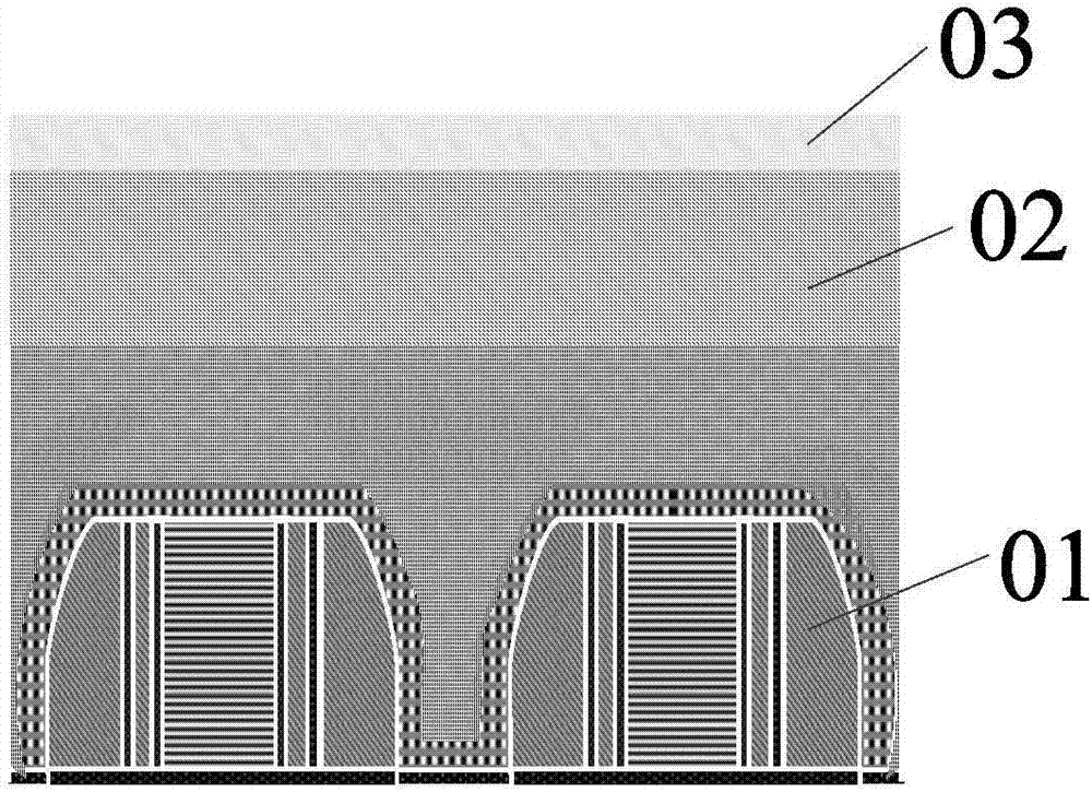
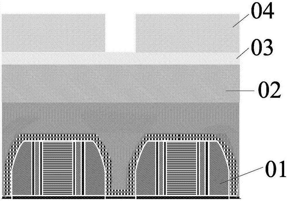
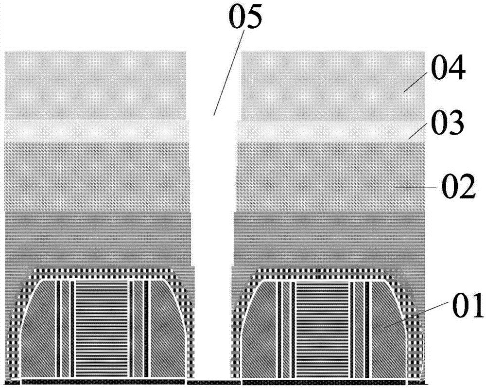
[0036] Step 1: Provide a CMOS device 10 with a silicon dioxide layer 90 on the CMOS device 10, first deposit an etch stop layer 20 on its surface by CVD, and then use HARP and TEOS in a similar manner to form an interlayer dielectric layer 30, planarize the surface of the inner layer dielectric layer 30 and then deposit an anti-reflection layer 40, deposit a second photoresist on the anti-reflection layer 40, use a through-hole mask for photolithography and then etch, use plasma Gas etching, etching gas including CF 4 and CH 2 f 2 , etching the anti-reflection layer 40, the inner layer dielectric layer 30...


PUM


Abstract

The invention provides a through hole manufacturing method beneficial to filling. An etch stop layer, an inner layer dielectric layer and an antireflection layer are deposited on the surface of a semiconductor device in sequence; a first through hole is etched in the antireflection layer, the inner layer dielectric layer and a part of etch stop layer; the bottom of the first through hole is etched to reach a silicon dioxide layer to form second through hole; the second through hole is filled with an antireflection material; a third through hole, the outlet caliber of which is greater than that of the second through hole, is photo-etched; the bottom of the third through hole is etched to reach the silicon dioxide layer of the semiconductor device to form a fourth through hole; the residual antireflection material in the fourth through hole is removed to form a fifth through hole; and the fifth through holes is continuously etched. According to the through hole manufacturing method provided by the invention, the key dimensions of the upper part through holes are enlarged to form a through hole appearance with a relatively large opening, thereby reducing negative influences to the subsequent process caused by high-aspect ratio, further lowering through hole filling difficulty caused by subsequent metal tungsten, and enlarging the subsequent process window.

Description

technical field [0001] The invention relates to the field of semiconductor technology, in particular to a method for making a through hole which is beneficial for filling. Background technique [0002] With the development of CMOS devices to 40nm and below nodes, the critical dimension (CD) of the through hole (CT) needs to be reduced correspondingly with the reduction of the pitch size of the through hole. Followed by the further increase of the aspect ratio (ARratio), the key index of via etching and filling, it brings great challenges to our traditional etching and filling process. [0003] The specific implementation steps of the existing through-hole etching are: after the formation of the CMOS device 01, use the through-hole etching stop layer 02 (CESL, CT Etch Stop Layer), HARP (High aspect ratio process, high aspect ratio process), TEOS (tetraethoxysilanc , tetraethylorthosilicate) and other CVD (chemical film formation) methods to form the inner layer dielectric la...

Claims


Application Information

Patent Timeline
Patent Type & Authority Applications(China)
IPC IPC(8): H01L21/768
CPCH01L21/76802H01L21/76804
Inventor 孙磊黄君
Owner SHANGHAI HUALI MICROELECTRONICS CORP
Why Eureka
Try Eureka