Battery connector for solving poor welding, and manufacturing method thereof

A technology of battery connector and manufacturing method, which is applied in the direction of electrical connection of printed components, connection, fixed connection, etc., can solve problems such as board scrapping, copper skin falling, and copper foil heating time for a long time, so as to reduce maintenance costs and strengthen The output of good products and the effect of solving poor welding problems

Inactive Publication Date: 2017-09-15
ZHENGZHOU YUNHAI INFORMATION TECH CO LTD
View PDF4 Cites 1 Cited by
  • Summary
  • Abstract
  • Description
  • Claims
  • Application Information

AI Technical Summary

Problems solved by technology

For the existing battery connector, in order to improve the welding effect, it is necessary to increase the welding time. However, if the welding time is increased, the copper foil will be heated for too long, which will cause the copper skin to fall off and cause the plate card scrapped

Method used


Image

  • Battery connector for solving poor welding, and manufacturing method thereof
  • Battery connector for solving poor welding, and manufacturing method thereof
  • Battery connector for solving poor welding, and manufacturing method thereof

Examples


Embodiment 1

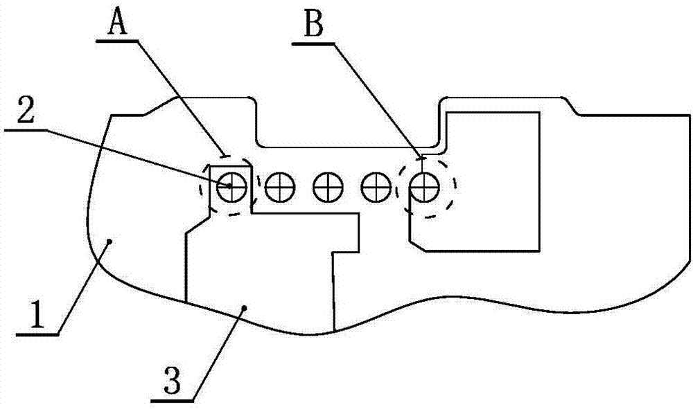
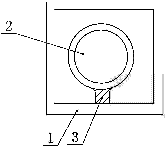
[0027] Embodiment one: if image 3 As shown, there is one line-shaped copper foil, and the width of the line-shaped copper foil 3 is less than half of the diameter of the pin socket. The line-shaped copper foil absorbs less heat, reduces the heat dissipation rate, and provides sufficient run-off time for soldering, so the pins are soldered firmly and avoid the occurrence of poor soldering.

Embodiment 2

[0028] Embodiment two: if Figure 4 As shown, the line-shaped copper foil includes several strips. And the width of each line-shaped copper foil 3 is less than half of the diameter of the pin socket. The line-shaped copper foil absorbs less heat, reduces the heat dissipation rate, and provides sufficient run-off time for soldering, so the pins are soldered firmly and avoid the occurrence of poor soldering.

[0029] A manufacturing method for solving poorly welded battery connectors, comprising the following steps:

[0030] Step S1: Drill through holes / blind holes on PCB1, and some of the through holes are used as pin jacks. In order to ensure the effect of copper sinking, the drilled through holes / blind holes are ground, swollen and decontaminated to prevent burrs, air bubbles and residues in the through holes / blind holes. The burr in the hole is removed by grinding the hole. After swelling treatment, the air bubbles are removed, and at the same time, the inner wall of the...


PUM


Abstract

The invention discloses a battery connector for solving poor welding, and a manufacturing method thereof. The battery connector comprises a PCB, wherein copper foil is arranged between Pins and the PCB, the copper foil outside Pin jacks is line-shaped, one end of the line-shaped copper foil is in contact with each Pin, and the rest part of the copper foil is attached to and fixed on the PCB. The manufacturing method comprises the steps of: S1, drilling through holes / blind holes in the PCB, wherein part of the through holes serve as the Pin jacks; S2, plating copper to form in-hole copper foil; S3, plating copper to form outer-hole copper foil; S4, and inserting the Pins into the Pin jacks subjected to copper plating. According to the battery connector and the manufacturing method thereof, the area of the copper foil is reduced while other parts remain unchanged, and the original surface-type copper foil is changed into the line-shaped copper foil, thus the reduction of heat absorbed by the cooper foil in a welding region is realized, the tin soldering effect is improved, and the welding quality is ensured. That is, the large copper foil area in the welding region is reduced to decrease the heat absorbed by the cooper foil, the absorption ability of the copper foil is decreased when the area of the copper foil is reduced, and the heat dissipation of the Pins welded on the connector is slowed down, thereby achieving the effect of satisfying the tin soldering requirement.

Description

technical field [0001] The invention relates to the technical field of printed circuit boards, in particular to a battery connector and a manufacturing method for solving poor welding. Background technique [0002] At present, the battery connectors of existing products often have poor welding, and sometimes the defective rate is even as high as about 30%. Such as figure 1 The areas marked A and B are the locations of bad pins. For the existing battery connector, in order to improve the welding effect, it is necessary to increase the welding time. However, if the welding time is increased, the copper foil will be heated for too long, which will cause the copper skin to fall off and cause the plate Card scrapped. Contents of the invention [0003] In order to overcome the problems existing in the prior art, the present invention provides a battery connector and a manufacturing method for solving poor welding. [0004] The technical solution adopted by the present invent...

Claims


Application Information

Patent Timeline
Patent Type & Authority Applications(China)
IPC IPC(8): H05K1/11H05K3/34H01R12/51H01R43/02
CPCH05K1/114H01R12/51H01R43/0256H05K3/3415
Inventor 张小行
Owner ZHENGZHOU YUNHAI INFORMATION TECH CO LTD
Why Eureka
Try Eureka