
V

A current measurement and current detection technology, which is applied in the direction of measuring devices, measuring electrical variables, voltage/current isolation, etc., can solve problems such as large errors in current values, and achieve low measurement accuracy, large dynamic range, and small power consumption and volume. Effect

Inactive Publication Date: 2017-09-19
CHONGQING UNIV
View PDF5 Cites 10 Cited by
  • Summary
  • Abstract
  • Description
  • Claims
  • Application Information

AI Technical Summary

Problems solved by technology

However, in actual measurement, the cable to be tested is usually eccentric (placed) between the center point in the circular hole between the "Hall sensor array" and the center of the circular hole, so that the current value obtained by the above calculation method There is a large error

Method used


Image

  • V
  • V
  • V

Examples


Embodiment

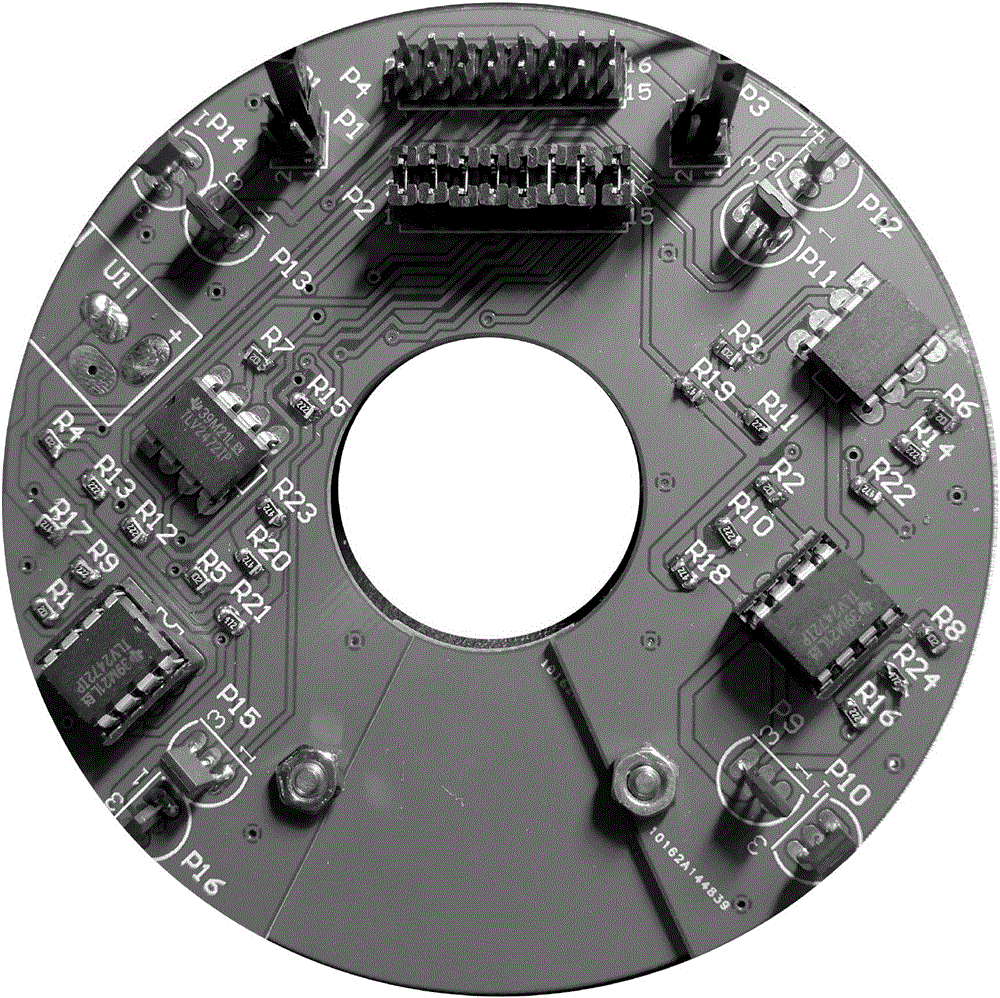
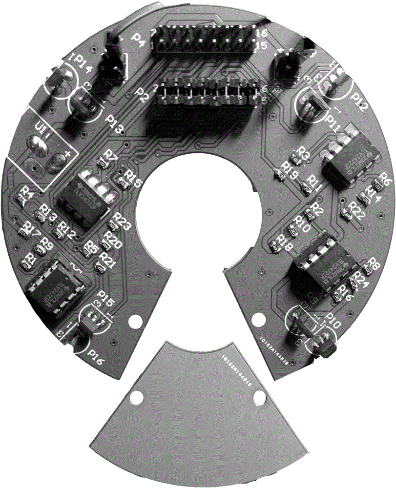
[0104] Embodiment: the current measuring method of the present invention adopts Figure 1 to Figure 9 The structure of the current sensor is shown in the structure.

[0105] First put the cable to be detected into the hole in the middle of the mounting base 1 of the current sensor, and then use screws to fix the small fan-shaped patch in the current sensor. The figure after the fixed connection is as follows figure 2 shown.

[0106] The detected current is generated by the DC power supply DLM 8-450E-M1 such as Figure 11 shown.

[0107] Set the DC current output to 100A, measure the output current with the PAC12 AC and DC current clamp, select the gear as 1mV / A, and the output of the DC clamp is as follows: Figure 12 shown.

[0108] Next, the current curves are calculated using Ampere's loop law, fast estimation method, and exact calculation method, respectively.

[0109] An example using the current measuring method of the present invention:

[0110] The equivalent co...


PUM


Abstract

The present invention discloses a current measurement method. The method comprises the step of cable current measurement through adoption of a current sensor. The current sensor comprises an installation seat, a current detection module, a DSP signal processor, an oscilloscope, a voltage follower and a resistive divider. The method also comprises the following steps: S1: four current detection units are employed to measure four measurement points (Bx, By), and then the resultant field B of each point is obtained according to the each point (Bx, By); S2, the ratios, kx, ky, of the resultant fields of two measurement points on the installation seat on the same vertical direction are calculated; S3, central point coordinates (x0, y0) of the portion, located in a punched hole, of a cable to be measured are calculated; S4, after the central point coordinates (x0, y0) of the portion, located in the punched hole, of the cable to be measured are calculated, distances between each measurement point and the (x0, y0) are calculated, and the current values of the four measurement points are calculated; and S5, the average value of the four current values is obtained, and the current value of the cable is obtained. The current value measured through the current measurement method is more accurate.

Description

technical field [0001] The invention relates to the field of electric parameter measurement, in particular to a current measurement method. Background technique [0002] The current detection of the distribution network is the basis for the safe operation of the system. Usually, the normal operating current of the distribution network is several kA, and the current is as high as tens of kA when a short-circuit fault occurs. Traditional electromagnetic sensors cause measurement inaccuracy due to the bandwidth and saturation of the iron core, and it has great limitations in the measurement of currents containing DC and harmonics. For the requirement of large dynamic range, large bandwidth, and simultaneous measurement of AC and DC flow, the shunt method needs to be connected to the circuit to be tested, which is inconvenient to install; the Rogowski coil based on electromagnetic induction cannot measure DC flow; the optical fiber current sensor has unstable working stability. ...

Claims


Application Information

Patent Timeline
IPC IPC(8): G01R19/25G01R15/04G01R15/20
CPCG01R15/04G01R15/202G01R19/25
Inventor 张淮清顾善匀李非凡秦领陶阳陈琳宋芳
Owner CHONGQING UNIV
Learn More