Angular-clamping biradial electron beam angle logarithmic plane zigzag slow-wave line slow-wave structure

A technology of meandering slow wave and slow wave structure, which is applied in the field of radial beam traveling wave tube slow wave system, can solve problems such as difficult processing, difficult processing of protrusions, and fracture of quartz dielectric substrates, so as to reduce processing difficulty and save Dielectric substrate, effect of high electron efficiency

Inactive Publication Date: 2017-09-19
UNIV OF ELECTRONICS SCI & TECH OF CHINA
View PDF5 Cites 14 Cited by
  • Summary
  • Abstract
  • Description
  • Claims
  • Application Information

AI Technical Summary

Problems solved by technology

However, the above-mentioned scheme has the problem of serious processing difficulties, specifically: first, when processing the quartz dielectric plate, it is very difficult to process "protrusions of a certain height at the position coincident with the microstrip slow-wave structure"; Second, the material of the angular radial logarithmic meander line is metal, which exists during the assembly of the entire tube, and cannot be assembled by mechanical clamping. The quartz dielectric substrate of the microstrip line structure slow wave system is welded as a whole Due to the uniformity of solder flow, the difference in expansion coefficient between quartz and metal, etc., it is easy to cause the fracture of the quartz dielectric substrate, resulting in the failure of the slow wave system

Method used


Image

  • Angular-clamping biradial electron beam angle logarithmic plane zigzag slow-wave line slow-wave structure
  • Angular-clamping biradial electron beam angle logarithmic plane zigzag slow-wave line slow-wave structure
  • Angular-clamping biradial electron beam angle logarithmic plane zigzag slow-wave line slow-wave structure

Examples


Embodiment Construction

[0041] The solutions of the present invention will be further described in detail below in conjunction with the accompanying drawings and specific embodiments.

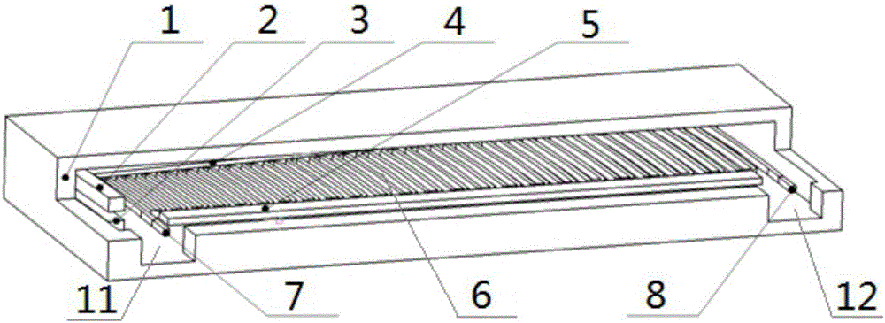
[0042] like figure 1 As shown, a double-radial electron beam angularly clamped angle logarithmic plane meandering slow wave line slow wave structure, including a metal cavity 1, and an angle logarithmic metal plane meandering slow wave line located inside the metal cavity 1 6. Upper ideal cathode 2, lower ideal cathode 3, medium support rod one 4, medium support rod two 5.

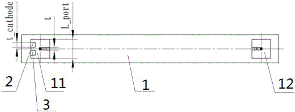
[0043] like figure 2 As shown, the metal cavity 1 is provided with an input port 11 and an output port 12, and the input port 11 and the output port 12 are all communicated with the inside of the metal cavity 1; the metal cavity 1 is a cuboid, and the input port 11 and the The output ports 12 are respectively located at the left and right ends of the front of the metal cavity 1 , and both the input port 11 and the output port 12 are squares wit...


PUM


Abstract

The invention discloses an angular-clamping biradial electron beam angle logarithmic plane zigzag slow-wave line slow-wave structure, and relates to the field of radial beam traveling-wave tube systems. The structure comprises a metal cavity, an angle logarithmic metal plane zigzag slow-wave line, an upper ideal cathode, a lower ideal cathode, a first medium supporting rod, and a second medium supporting rod. The structure solves a problem of an ineffective angle logarithmic micro-strip slow-wave structure in a working process of a radial beam traveling-wave tube, which is caused by a condition that a defocused electron beam is liable to bombard a logarithmic micro-strip and causes the fusion of the logarithmic micro-strip.

Description

technical field [0001] The invention belongs to the field of radial-beam traveling-wave tube slow-wave systems, in particular to a beam-wave interaction system for radial-beam traveling-wave tubes. Background technique [0002] The traveling wave tube in the electric vacuum microwave power device has the characteristics of wide operating frequency band, large output power, high interaction efficiency and long service life. It is widely used in electronic countermeasures and military-civilian communications. . [0003] The radial beam TWT based on the angular logarithmic slow-wave structure of the microstrip line has the characteristics of low operating voltage, wide operating frequency band, and small volume. The thickness of the microstrip line on the board used in the angle-logarithmic microstrip slow-wave structure is in the range of (0.004-0.018) mm. [0004] The patent No. 201611144229.8 discloses "angle radial logarithmic meander microstrip slow-wave structure loaded...

Claims


Application Information

Patent Timeline
Patent Type & Authority Applications(China)
IPC IPC(8): H01J23/24
CPCH01J23/24
Inventor 宫玉彬李新义王战亮魏彦玉何腾龙王禾欣师凝洁许多
Owner UNIV OF ELECTRONICS SCI & TECH OF CHINA
Why Eureka
Try Eureka