Granulator

A granulator and granulation technology, applied in coatings, epoxy resin coatings, etc., can solve the problems of wear on the inner wall of the barrel, poor wear resistance, etc., and achieve long service life, enhanced wear resistance, and novel structural design. Effect

Inactive Publication Date: 2017-09-22
合肥英源新材料科技有限公司
View PDF3 Cites 2 Cited by
  • Summary
  • Abstract
  • Description
  • Claims
  • Application Information

AI Technical Summary

Problems solved by technology

[0004] At the same time, the barrels of existing granulators are generally made of aluminum alloy. The barrels ma

Method used


Image

  • Granulator
  • Granulator

Examples


Embodiment 1

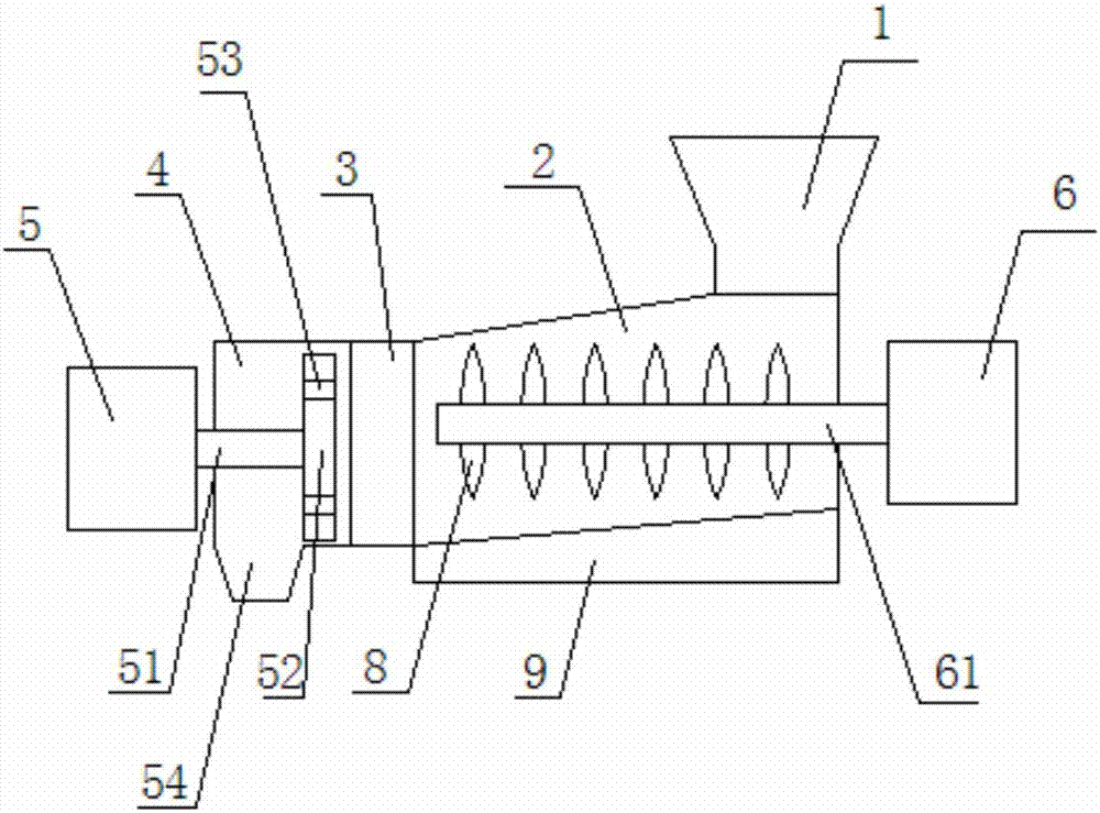
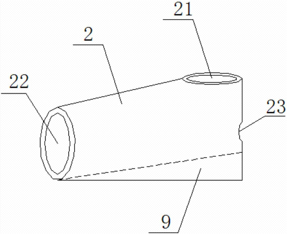
[0026] like Figure 1 to Figure 2 As shown, the present invention provides a granulator, comprising: a feed hopper 1, a barrel 2 communicated with the feed hopper 1, a buffer chamber 3 communicated with the feed barrel 2, and a granulation chamber 4 communicated with the buffer chamber 3 . The raw material enters the barrel 2 from the feed hopper 1, and is transported to the buffer chamber 3 after being heated in the barrel 2. After being squeezed in the buffer chamber 3, it enters the granulation chamber 4 for granulation.

[0027] One side of the barrel 2 is provided with a first motor 6 . The first motor 6 is connected to the first rotating shaft 61 . The first rotating shaft 61 extends into the inside of the barrel 2 . The helical blade 8 is arranged on the first rotating shaft 61 . The first motor 6 drives the first rotating shaft 61 to rotate, and transmits the raw material to the buffer chamber 3 through the helical blade 8 .

[0028] A second motor 5 is provided o...

Embodiment 2

[0033] A manufacturing process of a granulator barrel, the steps are as follows:

[0034] ① Roll forming of barrel

[0035] Ductile cast iron is used as raw material, and the barrel is made by roll forming technology. One end of the barrel has a vertical opening, and the other end has a horizontal opening;

[0036] ②, Spraying treatment on the inner wall of the barrel

[0037] Use electrostatic spraying technology to spray the inner wall of the barrel, and leave it for 10 days naturally after spraying;

[0038] The preparation method of the spraying liquid is: 25 parts of epoxy resin, 5 parts of titanium dioxide, 10 parts of methylolated phenol, 5 parts of leveling agent, 15 parts of solvent, 5 parts of 5,7-dihydroxyflavone and trifluoropropanesulfone Put 5 parts of Long in a mixing container, stir and mix evenly;

[0039] ③, heat treatment

[0040] Place the barrel in a heat treatment furnace for heat treatment at 200°C for 0.5h, then let it cool naturally.


PUM


Abstract

The invention provides a granulator and relates to the technical field of granulation. The granulator comprises a feeding hopper, a material cylinder, a buffer chamber and a granulation chamber. A first motor is arranged on one side of the material cylinder. A first rotary shaft is connected to the first motor. The first rotary shaft extends into the material cylinder. Spiral blades are arranged on the first rotary shaft. A second motor is arranged on one side of the granulation chamber and connected with a second rotary shaft. The second rotary shaft extends into the granulation chamber. A granulation cutter is arranged at the end of the second rotary shaft. Granulation holes are formed in the granulation cutter. The height of the inner wall, close to one side of the buffer chamber, in the material cylinder is lower than that of the inner wall, close to one side of the first motor, in the material cylinder. A heater is arranged at the bottom of the material cylinder. Through the design of a material cylinder special structure, all the raw materials in the material cylinder enter the buffer chamber under the effect of the dead weight, and it can be avoided that the raw materials are deposited at the bottom of the material cylinder and consequentially the materials are wasted; and the extrusion strength of the raw materials in the buffer chamber can be increased, and the generation speed of plastic particles is increased.

Description

technical field [0001] The invention relates to the technical field of granulation, in particular to a granulator. Background technique [0002] A granulator is a machine that turns plastic film and other raw materials into plastic granules. Its working principle is to transport plastic film and other raw materials to the material cylinder for heating and melting, after the raw materials are melted, they are extruded in the buffer chamber, and then form plastic granules through the granulation holes on the cutter. [0003] During the granulation process of the granulator currently on the market, after the raw material enters the material barrel, it passes through the screw blade on the rotating shaft arranged in the material barrel to guide the raw material to the buffer chamber. However, in the actual production process, raw materials are easy to deposit at the bottom of the barrel, and this part of raw materials cannot be sent into the buffer chamber, resulting in waste o...

Claims


Application Information

Patent Timeline
IPC IPC(8): B29B9/06B29C47/66C09D163/00C09D7/12
CPCB29B9/06B29C48/681C08K5/13C08K5/435C08K13/02C08K2003/2241C09D163/00
Inventor 邬家银
Owner 合肥英源新材料科技有限公司
Why Eureka
Try Eureka