Oil sludge pyrolysis continuous feeding device

A feeding device and pyrolysis technology, which is applied in pyrolysis treatment of sludge, petroleum industry, indirect heating and dry distillation, etc., can solve problems such as poor fluidity, high sludge viscosity, and inability to transport sludge, and achieve error elimination, low cost, Simple operation effect

Pending Publication Date: 2017-09-22
BEIJING SHENYUAN ENVIRONMENTAL PROTECTION CO LTD
View PDF0 Cites 0 Cited by
  • Summary
  • Abstract
  • Description
  • Claims
  • Application Information

AI Technical Summary

Problems solved by technology

[0003] The process of producing oil, gas and charcoal by anaerobic pyrolysis of oily sludge has its advanced nature, so that all the organic matter in the sludge can be treated, the oil can be recovered, and the final disposal of harmless and resourceful can be realized. However, in the actual production process, due to The oil sludge has high viscosity and poor fluidity, and the feeding system of ordinary garbage or municipal sludge cannot transport the oil sludge

Method used


Image

  • Oil sludge pyrolysis continuous feeding device
  • Oil sludge pyrolysis continuous feeding device
  • Oil sludge pyrolysis continuous feeding device

Examples


Embodiment Construction

[0028] It should be understood that the embodiments of the invention shown in the exemplary embodiments are illustrative only. Although only a few embodiments have been described in detail in the present invention, those skilled in the art will readily appreciate that many modifications are possible without materially departing from the teachings of the subject matter of the invention. Accordingly, all such modifications are intended to be included within the scope of this invention. Other substitutions, modifications, changes and deletions can be made to the designs, operating conditions and parameters of the following exemplary embodiments without departing from the gist of the present invention.

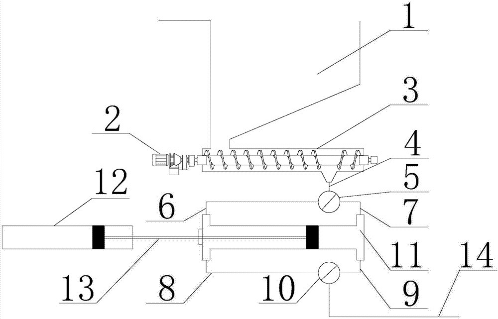
[0029] Such as figure 1 The shown oil sludge pyrolysis continuous feeding device has a storage bin 1, the storage bin 1 has an inlet and an outlet, and an arch breaking device (not shown) is arranged in the storage bin 1 to prevent the oil sludge from entering the The cavity is ...


PUM


Abstract

The invention discloses an oil sludge pyrolysis continuous feeding device. The oil sludge pyrolysis continuous feeding device is provided with a material storage bin, a pre-pressing screw and a bidirectional plunger pump, wherein the material storage bin is provided with an inlet and an outlet; the pre-pressing screw is provided with an inlet and an outlet, the inlet of the pre-pressing screw is communicated with the outlet of the material storage bin, and a motor is arranged at one side of the pre-pressing screw; the bidirectional plunger pump is provided with a first inlet, a second inlet, a first outlet and a second outlet, the first inlet and the second inlet thereof are respectively connected with a first material inlet pipe and a second material inlet pipe, the first outlet and the second outlet are respectively connected with a first material outlet pipe and a second material outlet pipe, the first material pipe and the second material pipe are communicated with the outlet of the pre-pressing screw through a material inlet main pipe, a first reversing valve is arranged among the first material inlet, the second material inlet pipe and the material inlet main pipe, the first material outlet pipe and the second material outlet pipe are connected with a material outlet main pipe, and a second reversing valve is arranged among the first material outlet pipe, the second material outlet pipe and the material outlet main pipe. The oil sludge pyrolysis continuous feeding device has the advantages that the high-viscosity oil sludge can be continuously fed in the pyrolysis technology, the reliability, efficiency and controllability are realized, and the oil sludge pyrolysis continuous feeding device is suitable for being popularized in a large-scale way.

Description

technical field [0001] The invention relates to the technical field of environment, energy and environmental protection, in particular to a continuous feeding device for oil sludge pyrolysis. Background technique [0002] The annual output of oily sludge in my country is huge, and there are three main ways of generation: during the extraction of crude oil, during the production and transportation of crude oil, and in the sewage treatment plant of the refinery. Among them, in the process of crude oil extraction, the oil sludge output is 0.5% to 1% of the crude oil output. According to the figures from the National Bureau of Statistics, the total crude oil extraction in my country in 2014 was 2.1×10 8 tons, and the output of oil sludge is about 2 million tons, and many oil fields in my country have entered the end stage of exploitation, and the proportion of oil sludge production will be even greater. The oil content of oily sludge is generally between 20% and 50%, and the wa...

Claims


Application Information

Patent Timeline
IPC IPC(8): C02F11/10C10B53/00C10B47/44C02F103/10C02F103/36
CPCY02W10/40C02F11/10C02F2103/10C02F2103/365C10B47/44C10B53/00
Inventor 房凯巴玉鑫吴小飞王惠惠牛明杰王鑫刘春亚吴道洪
Owner BEIJING SHENYUAN ENVIRONMENTAL PROTECTION CO LTD
Why Eureka
Try Eureka