Self-powered type magnetorheological damper

A magnetorheological shock absorber, self-powered technology, applied in the direction of shock absorbers, shock absorbers, springs/shock absorbers, etc., can solve the problems of many external accessories, large space occupation, complex structure, etc., and achieve the overall structure Small, easy to arrange and install

Inactive Publication Date: 2017-09-26
JIANGSU UNIV
View PDF9 Cites 23 Cited by
  • Summary
  • Abstract
  • Description
  • Claims
  • Application Information

AI Technical Summary

Problems solved by technology

A Chinese patent (CN102797655A) discloses a power generation system for automobile piezoelectric shock absorbers, which uses the up and down movement of the piston rod of the shock absorber to pump the oil into the high-pressure tank to form the hydraulic energy of the oil, and uses the hydraulic energy of the oil to drive the motor to drive The rotation of the rotating shaft changes the pressure of the oil in the hydraulic cylinder, and the quasi-harmonic vibration is formed by the pressure change of the oil to drive the piston to produce quasi-harmonic vibration compressive stress on the piezoelectric stack, so that the positive piezoelectric effect of the piezoelectric ceramic will The mechanical energy is converted into electrical energy, and the rectifier bridge and the energy storage are connected in turn to complete the function of the piezoelectric energy conversion system; this structure can theoretically realize the energy recovery of the vibrator, but there are complex structures and low power generation efficiency due to multiple energy conversions question
Similar to the Chinese patent (CN102926956A), the related method of utilizing hydraulic energy storage for energy recovery basically uses the accumulator to store the hydraulic energy in the shock absorber, and when a certain pressure requirement is reached, the accumulator is used to store the hydraulic energy in the shock absorber. The high-pressure liquid drives the hydraulic motor to rotate, converts the hydraulic energy into kinetic energy, thereby drives the generator to rotate, and realizes energy recovery and utilization; these technical solutions have the characteristics of too many additional accessories and occupying a large space
[0004] Whether it is the above-mentioned patents or some other existing patented technologies, the energy recovery of the shock absorber can be realized, but most of them have problems that are difficult to overcome in practical applications, such as too low power generation efficiency, too large space size, and affecting the original structure of the shock absorber. There is a defect in the function of the shock absorber

Method used


Image

  • Self-powered type magnetorheological damper
  • Self-powered type magnetorheological damper

Examples


Embodiment Construction

[0019] The present invention will be further described below in conjunction with the accompanying drawings and specific embodiments. It should be understood that the following specific embodiments are only for the present invention but not intended to limit the scope of the present invention.

[0020] It should be noted that the words "front", "rear", "left", "right", "upper" and "lower" used in this embodiment refer to the directions shown in the drawings.

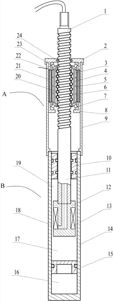
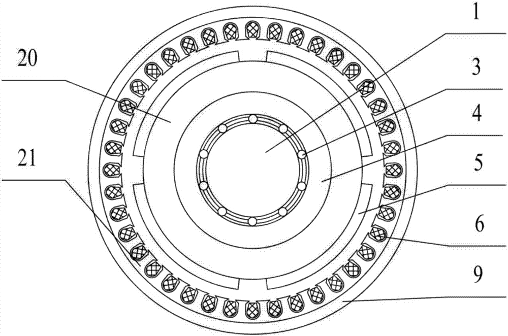
[0021] Such as figure 1 , 2 A self-powered magneto-rheological shock absorber is shown. The shock absorber includes a power generation chamber A, a vibration reduction chamber B and a piston rod. The power generation chamber A is welded to the cylinder body of the vibration reduction chamber B through the power generation chamber casing 9 14, the upper end, the piston rod is placed vertically in the power generation chamber A and the vibration reduction chamber B, and the screw part 1 of the piston rod is in contact with...


PUM


Abstract

The invention discloses a self-powered magneto-rheological shock absorber, which comprises a power generation chamber, a vibration reduction chamber and a piston rod. Nuts and balls form a ball screw, and the polished rod part of the piston rod extends into the damping chamber through the seal; The rotor is connected, the outer circumference of the rotor is a stator core, and the stator core is fixedly connected to the inner wall of the housing of the power generation chamber. When the shock absorber is working, the liquid in the damping chamber generates a damping force through the damping channel, and the damping force is adjusted through the coil; the ball screw converts the reciprocating motion of the piston rod into a rotational motion, and the rotation of the rotor makes the stator winding cut the magnetic induction line to generate electricity, thereby Achieve energy recovery. The invention has a simple structure, takes up little space, realizes energy recovery without affecting the original damping performance of the shock absorber, and is convenient to popularize and use on vehicles.

Description

technical field [0001] The invention belongs to the technical field of machinery and motors, in particular to a magneto-rheological shock absorber with self-power supply function. Background technique [0002] With the continuous increase of global automobile production and the increasing popularity of automobiles, automobiles are becoming an indispensable means of travel for people. However, the energy utilization rate of automobiles cannot meet people's requirements, and a large amount of energy is wasted during automobile driving. Among them, the energy generated by the vibration of the car is mainly converted into heat energy and dissipated into the air through the damping of the shock absorber. According to the driving performance simulation of a typical car under different working conditions and the energy consumption of its suspension, it is found that when the vehicle travels on a C-class road at a speed of 20m / s for 20s, the passive suspension system consumes energ...

Claims


Application Information

Patent Timeline
Patent Type & Authority Applications(China)
IPC IPC(8): F16F9/53F03G7/08
CPCF16F9/535F03G7/08
Inventor 何仁王乐乐
Owner JIANGSU UNIV
Why Eureka
Try Eureka