Heat management system and method of power battery pack

A technology of battery management system and thermal management system, applied in secondary batteries, secondary battery repair/maintenance, battery/fuel cell control devices, etc., can solve problems such as low efficiency, uneven temperature distribution, thermal runaway, etc., to achieve Unified thermal management of heating and cooling, convenient switching of current direction, fast cooling and heating effects

Pending Publication Date: 2017-09-29
江苏英耐杰新能源有限公司
View PDF7 Cites 12 Cited by
  • Summary
  • Abstract
  • Description
  • Claims
  • Application Information

AI Technical Summary

Problems solved by technology

Due to the large number of batteries required by electric vehicles and the limited loading space, the batteries must be closely arranged and connected. When the electric vehicle is running under different working conditions, the battery pack will be discharged at different rates and generate a large amount of heat at different heat generation rates. The accumulation of time and the influence of space will produce uneven heat accumulation, which will lead to the unbalanced operating environment temperature of the battery pack, especially in summer high temperature weather, the ambient temperature of the battery pack itself is very high, and in addition to operating under complex working conditions, It is more likely to cause excessive temperature and uneven temperature distribution of the battery pack system
If the entire battery pack cannot be dissipated in time at high temperatures, the excessively high operating temperature and the excessively large temperature difference cannot be alleviated, which will reduce the charge-discharge cycle life of the battery system and affect the power and energy performance of the battery. Can cause thermal runaway, which ultimately affects the safety and reliability of the battery pack
[0003] At present, the thermal management methods of power battery packs on the market are mostly completed by two sets of devices. Generally, resistance heaters are used for heating. The heating efficiency of this method is not high and the temperature difference is large.
Cooling generally adopts forced air cooling or liquid cooling. The forced air cooling mainly draws the air-conditioning wind in the car or the air in the environment into the battery pack, and discharges the hot air out of the battery pack to achieve the purpose of cooling the battery cells. This solution The low temperature difference in efficiency is large, and the protection level of the battery pack cannot be guaranteed
Liquid cooling is to use heat-conducting materials to conduct the heat of the battery cell to the refrigerant, and take the heat away through the refrigerant. This method is costly, complicated in structure, and difficult to maintain

Method used


Image

  • Heat management system and method of power battery pack
  • Heat management system and method of power battery pack

Examples


Embodiment 1

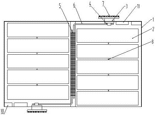
[0025] Such as figure 1 and figure 2 As shown, a thermal management system of a power battery pack includes a thermistor 8 , a semiconductor refrigeration device 3 , a heat pipe 6 , a circuit control device and a battery management system 11 .

[0026] Both the thermistor 8 and the heat pipe 6 are installed in the battery case 1, and are located between the battery modules 2, the thermistor 8 is not less than two, and the adjacent battery modules 2 are installed With thermistor 8;

[0027] The heat pipe 6 is an L-shaped heat pipe, one end of the heat pipe 6 is connected to the heat absorbing sheet 5 located in the center of the battery case 1, and the other end is connected to the semiconductor refrigeration device 3 installed on the outside of the battery case 1 through the aluminum plate 4. The device 3 is connected to the power converter 10 through a circuit control device; the heat pipe 6 and the semiconductor refrigeration device 3 are provided with two groups, and the...

Embodiment 2

[0031] A management method for a thermal management system of a power battery pack, comprising the following steps:

[0032] S1, the thermistor 8 detects the temperature inside the battery box 1;

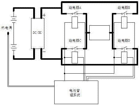
[0033] S2. When the temperature detected by the thermistor 8 exceeds the preset value of the battery management system 11, the battery management system 11 outputs a positive DC voltage by closing relay A and relay D, and starts the semiconductor cooling mode, that is, the air in the battery box and the The heat-absorbing sheet 5 and the heat pipe 6 exchange heat, transfer the heat to the aluminum plate 4, and exchange heat again through the cold end of the semiconductor refrigeration device 3, and the heat moves to the hot end through the thermoelectric cooling effect, and the hot end of the semiconductor refrigeration device 3 and the The heat sink 7 is connected, and the heat sink 7 dissipates heat to the environment through convection heat exchange with the natural wind when the...


PUM


Abstract

The invention relates to a management system of a battery pack, in particular to a heat management system and method of a power battery pack. The system comprises a thermistor, a semiconductor refrigeration device, a heat pipe, a circuit control device and a battery management system, wherein the thermistor and the heat pipe are arranged in a battery box body and are positioned between battery modules; one end of the heat pipe is connected with a heat absorption sheet positioned between the battery modules; the other end of the heat pipe is connected with the semiconductor refrigeration device arranged at the outer side of the battery box body through an aluminum plate; the semiconductor refrigeration device is connected with a power supply converter through the circuit control device; the circuit control device provides positive voltage and reverse voltage for the semiconductor refrigeration device; the thermistor and the circuit control device are connected with the battery management system; the battery management system monitors the temperature inside the battery box body. The two-way control of refrigeration and heating on the battery pack can be realized by using one set of system; the structure is simple; the cost is low; the reliability is high; the maintenance is easy; the service life is long; the temperature control is good.

Description

technical field [0001] The invention relates to a battery pack management system, in particular to a power battery pack thermal management system and management method. Background technique [0002] The power battery is the only power source of electric vehicles, and the temperature has a great influence on the performance, safety and service life of the power battery. Due to the large number of batteries required by electric vehicles and the limited loading space, the batteries must be closely arranged and connected. When the electric vehicle is running under different working conditions, the battery pack will be discharged at different rates and generate a large amount of heat at different heat generation rates. The accumulation of time and the influence of space will produce uneven heat accumulation, which will lead to the unbalanced operating environment temperature of the battery pack, especially in summer high temperature weather, the ambient temperature of the battery...

Claims


Application Information

Patent Timeline
Patent Type & Authority Applications(China)
IPC IPC(8): H01M10/613H01M10/625H01M10/635H01M10/6572H01M10/6552H01M10/42B60L11/18
CPCH01M10/425H01M10/613H01M10/625H01M10/635H01M10/6552H01M10/6572B60L58/24H01M2010/4278H01M2010/4271Y02T10/70Y02E60/10
Inventor 张进李书坤殷志华杨永强顾长德洪荔
Owner 江苏英耐杰新能源有限公司
Why Eureka
Try Eureka