Broadband microwave switch duplex circuit with low video feed through leakage

A microwave switch and duplex circuit technology, applied in electrical components, impedance networks, etc., can solve problems such as normal signal transmission interference, and achieve the effects of good production consistency, low insertion loss, and simple circuit

Inactive Publication Date: 2017-09-29
THE 41ST INST OF CHINA ELECTRONICS TECH GRP
View PDF7 Cites 2 Cited by
  • Summary
  • Abstract
  • Description
  • Claims
  • Application Information

AI Technical Summary

Problems solved by technology

[0007] The invention provides a broadband microwave switch duplex circuit with low video feedthrough leakage, which solves the problem of low-frequency video feedthrough signal generated by rapid step change of bias voltage in the state of switch conversion in the prior art, and the normal transmission of the signal Interfering technical issues

Method used


Image

  • Broadband microwave switch duplex circuit with low video feed through leakage
  • Broadband microwave switch duplex circuit with low video feed through leakage
  • Broadband microwave switch duplex circuit with low video feed through leakage

Examples


Embodiment 1

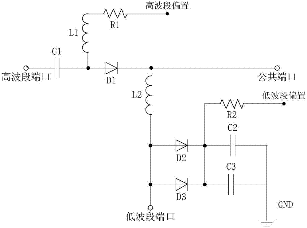
[0030] Such as figure 1 As shown, the broadband microwave switch duplex circuit with low video feedthrough leakage in this embodiment includes a high-band port 1, a high-band bias circuit, a low-band port 2, a low-band bias circuit and a common port 3, and the high-band The band bias circuit is arranged between the high-band port 1 and the common port 3, and the low-band bias circuit is arranged between the low-band port 2 and the common port 3;

[0031] The high-band bias circuit includes a first DC blocking capacitor C1 connected in series with the high-band port 1, a first PIN diode D1, and a high-band bias 4 connected in parallel with the high-band port 1, the high-band bias 4 connected between the first DC blocking capacitor C1 and the first PIN diode D1 through the first current limiting resistor R1 and the choke inductor L1;

[0032] The low-band bias circuit includes a low-band coupling inductor L2 connected in series with the low-band port 2, and a second PIN diode D...

Embodiment 2

[0037] Such as figure 1As shown, the specific working state of the broadband microwave switch duplex circuit with low video feedthrough leakage in this embodiment is: when the high-band bias 4 adds a positive voltage, and the low-band bias 5 adds the same negative voltage, the high-band bias The PIN diodes connected in series in the setting circuit and the PIN diodes connected in parallel in the low-band bias circuit are all turned on, so that the high-band port 1 realizes direct connection, and the low-band port 2 realizes isolation. At the same time, because the voltages of the two control terminals are the same, the potential on the path from the low-band port 2 to the common port 3 remains at zero potential. When the high-band bias 4 is applied with a negative voltage, and the low-band bias 5 is applied with the same positive voltage, the PIN diodes connected in series with the high-band bias circuit and the PIN diodes connected in parallel with the low-band bias circuit a...

Embodiment 3

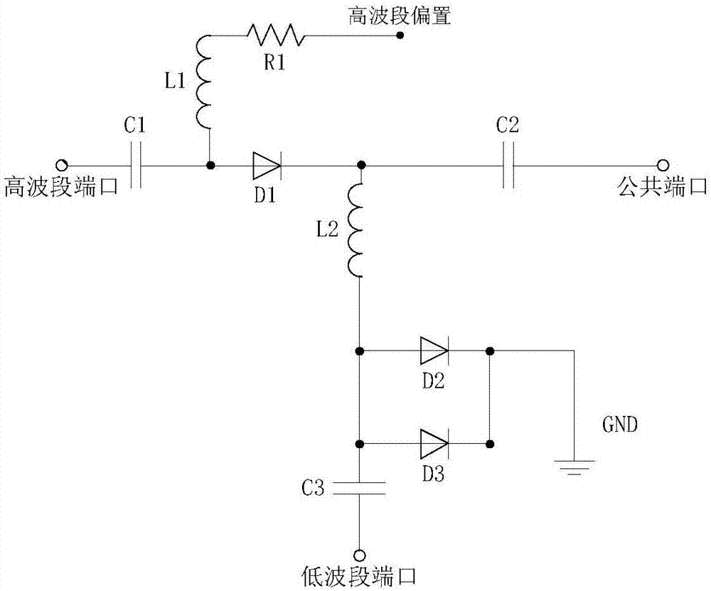
[0039] Such as figure 2 As shown, this embodiment is a schematic diagram of a simplified microwave switch duplex circuit. The PIN diodes are also connected in series and parallel, but the parallel PIN diodes in the low-band bias circuit are directly grounded, so that a relatively simple microwave switch duplex circuit can also be realized.

[0040] The specific working principle is: when the switch duplex circuit is biased, there is a DC voltage in the channel of the low-band port 2 and the common port 3, and a DC blocking capacitor needs to be added to the channel. At the same time, the rapid change of the driving voltage will generate a video signal on the channel. Feedthrough leakage. figure 2 The circuit can control the microwave switch duplex circuit only through one power-on bias terminal of the high-band bias circuit, and the drive is simple. This circuit is suitable for when the influence of video feedthrough leakage is not required or the minimum operating frequenc...


PUM


Abstract

The invention relates to a microwave switch duplex circuit, and specifically relates to a broadband microwave switch duplex circuit with low video feed through leakage. The broadband microwave switch duplex circuit comprises a high waveband port, a high waveband bias circuit, a low waveband port, a low waveband bias circuit and a public port; a high waveband PIN diode adopts a serial structure, a low waveband PIN diode adopts a parallel structure, the PIN diode control of the switch duplex circuit adopts a positive and negative balance power supply mode, and the technical problem that a bias voltage fast step change will generate a low-frequency video feed through signal at a switch conversion state to cause interference to the normal transmission of signals in the prior art is solved.

Description

technical field [0001] The invention relates to a microwave switch duplex circuit, in particular to a broadband microwave switch duplex circuit with low video feedthrough leakage. Background technique [0002] The operating bandwidth of microwave test instruments is getting wider and wider, because of the use of component bandwidth limitations and different processing methods for high and low band signals. In most cases, the transmitting channels of broadband microwave testing instruments are divided into high and low bands for signal generation and processing respectively. In the receiving channel of the signal, it is also necessary to convert and distribute the broadband microwave input signal to channels of different high and low bands for analysis and processing. Now, the minimum operating frequency of microwave and millimeter wave test instruments is getting lower and lower, and the minimum operating frequency of general test instruments is several kilohertz (kHz). In...

Claims


Application Information

Patent Timeline
Patent Type & Authority Applications(China)
IPC IPC(8): H03H9/70
CPCH03H9/70
Inventor 段喜东刘金现殷军姚廷明高栋李原程守梅
Owner THE 41ST INST OF CHINA ELECTRONICS TECH GRP
Why Eureka
Try Eureka