
Petroleum drilling machine tubing string automatic processing system

A technology for processing systems and drilling rigs, applied to the automatic control system of drilling, drilling pipes, rotary drilling rigs, etc., can solve the problems of high labor intensity, low transmission efficiency, high energy consumption, etc., and achieve the effect of improving the degree of automation

Inactive Publication Date: 2017-10-03
山东胜工检测技术有限公司 +1
View PDF11 Cites 12 Cited by
  • Summary
  • Abstract
  • Description
  • Claims
  • Application Information

AI Technical Summary

Problems solved by technology

[0003] The purpose of the present invention is to provide an automatic oil drilling rig pipe string automatic processing system for the automatic upgrading and transformation of oil drilling rigs, to realize the automation of the entire process of pipe string operation, and to solve the current transportation of drilling pipe strings from the ground to the drilling floor - the pipe string is in the There are high-altitude, multi-person operations in a series of operations such as making up, breaking out and tightening, collapsing, hanging and connecting, throwing off single roots and vertical roots on the drill floor—drilling during drilling—drilling during drilling—storage and withdrawal of vertical roots during drilling and tripping. Cooperate with the operation, the problems of high labor intensity, high risk and low efficiency; overcome the shortcomings of the existing drilling rig automation supporting schemes, such as the manual operation of the power winch, the low transmission efficiency of the automatic catwalk machine, and the high energy consumption.

Method used


Image

  • Petroleum drilling machine tubing string automatic processing system
  • Petroleum drilling machine tubing string automatic processing system

Examples


Embodiment Construction

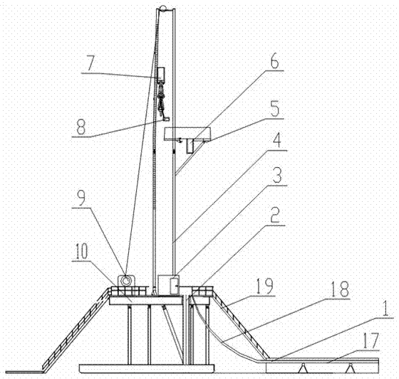
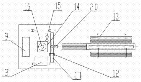
[0014] The present invention will be further described now in conjunction with the accompanying drawings. Oil drilling rig pipe string automatic processing system is mainly composed of drill floor 10, derrick 4, automatic catwalk machine 1, power mouse hole 2, turntable 14, drill floor manipulator 12, power slips 16, iron driller 15, power elevator 8, The second-floor platform is composed of manipulator 6, top drive 7, winch 9, and driller integrated control system 3.

[0015] Among them, the automatic catwalk machine 1 is installed in front of the power mouse hole 2, the power mouse hole 2 is installed in front of the turntable 14, the drill floor manipulator 12 is installed on the surface of the drill floor 10 through the guide rail 11, and the power slips 16 are installed on the turntable 14, the iron driller 15 is installed on the surface of the drill floor 10 on the side of the turntable 14, the power elevator 8 is installed on the lifting ring of the top drive 7, and the...


PUM


Abstract

The invention discloses a petroleum drilling machine tubing string automatic processing system. The petroleum drilling machine tubing string automatic processing system is mainly composed of a drill stand, a derrick, an automatic catwalk machine, a power rat hole, a rotary table, a drill stand manipulator, a power slip, an iron roughneck, a power elevator, a racking platform pipe-handling manipulator, a top drive, a winch and a driller integrated control system. After the petroleum drilling machine tubing string automatic processing system is matched to a petroleum drilling machine, automation of all tubing string operation processes of stand column connecting and stand column throwing, individual pipe connecting and individual pipe throwing, drilling, stand pipe storing and stand pipe fetching and the like during the drilling operation process is achieved. According to the invention, the automation degree of the drilling machine is increased, the problem that with respect to the existing drilling tubing string operation mode, many people need to cooperate with one another to work high above the ground, the labor intensity is large, the risk is high, and the efficiency is low is solved, and problems existing in the prior art that the power winch needs to be manually operated, the automatic catwalk machine is low in conveying efficiency and high in energy consumption are cvercome.

Description

technical field [0001] The invention belongs to the technical field of oil drilling equipment, and in particular relates to a safe and efficient oil drilling rig automatic processing system suitable for land drilling rigs. Background technique [0002] At present, the foreign string automation operating system has realized the automation of the whole process of string operation. Although local mechanization has been realized on the existing drilling rigs in China, which reduces the labor intensity of workers, the automation of the whole process of pipe string operation has not been realized, and the technical advantages of pipe string automation operating system have not been effectively utilized. Chinese invention patent ZL200820124227.7 discloses an oil drilling rig automation system, which can realize functions such as single root connection and stand root access in the process of drilling and running through the cooperative operation of various equipment, which improves ...

Claims


Application Information

Patent Timeline
Patent Type & Authority Applications(China)
IPC IPC(8): E21B3/00E21B19/00E21B19/15E21B19/16E21B19/18E21B44/00
CPCE21B3/00E21B19/00E21B19/155E21B19/16E21B19/18E21B44/00
Inventor 江正清王斌斌董怀荣李进付付广萌陈志礼
Owner 山东胜工检测技术有限公司
Learn More