
Multi-connecting-rod independent suspension for drive axle of commercial vehicle

An independent suspension and drive axle technology, applied in the automotive field, can solve the problems of poor bearing capacity, inability to ensure suspension bearing capacity, easy deformation, etc., and achieve the effects of improving bearing capacity, ensuring vehicle comfort, and reducing stress concentration

Active Publication Date: 2017-10-10
WUHAN UNIV OF TECH
View PDF10 Cites 6 Cited by
  • Summary
  • Abstract
  • Description
  • Claims
  • Application Information

AI Technical Summary

Problems solved by technology

[0007] Among the independent suspensions disclosed by CN203854440U and CN201685676U, it is a double-wishbone independent suspension structure, which has good suspension ride comfort, safety and comfort, but poor carrying capacity, and due to its shock absorber and spring elements Together they form a strut structure, which is easily deformed under a large force. In these two documents, the bearing capacity of the suspension cannot be guaranteed, and its application is only applicable to the front steering axle of commercial vehicles.

Method used


Image

  • Multi-connecting-rod independent suspension for drive axle of commercial vehicle
  • Multi-connecting-rod independent suspension for drive axle of commercial vehicle
  • Multi-connecting-rod independent suspension for drive axle of commercial vehicle

Examples


Embodiment Construction

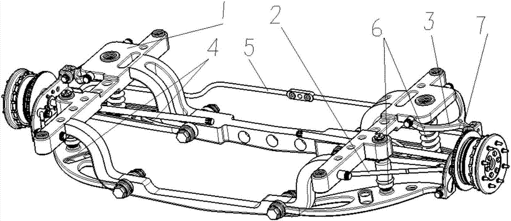
[0042] The specific implementation of the multi-link independent suspension for the commercial vehicle drive axle of the present invention will be described in further detail below with reference to the accompanying drawings, which will help those skilled in the art to understand the concept of the present invention and understand the technical principles, and help them implement.

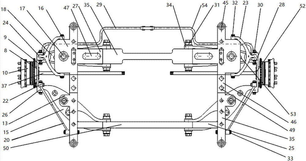
[0043] Such as Figure 2 to Figure 5 As shown, the multi-link independent suspension for a commercial vehicle drive axle described in the embodiment of the present invention includes a subframe assembly 1 for connecting with a frame longitudinal beam, an upper longitudinal tie rod assembly 2, an upper transverse Tie rod assembly 3 , lower cross tie rod assembly 4 , stabilizing tie rod assembly 5 , shock absorber spring assembly 6 and bearing block assembly 7 connected with wheel hub 10 .

[0044] The sub-frame assembly 1 mainly includes a sub-frame 35 with double longitudinal beams and double beam...


PUM


Abstract

Disclosed is a multi-connecting-rod independent suspension for a drive axle of a commercial vehicle. The multi-connecting-rod independent suspension for the drive axle of the commercial vehicle comprises an auxiliary vehicle frame assembly used for being connected with vehicle frame longitudinal beams, an upper longitudinal pulling rod assembly, an upper horizontal pulling rod assembly, a lower horizontal pulling rod assembly, a stable pulling rod assembly, an absorber spring assembly and a bearing base assembly. The auxiliary vehicle frame assembly mainly comprises an auxiliary vehicle frame with a structure of double longitudinal beams and double horizontal beams. The auxiliary vehicle frame comprises an auxiliary vehicle frame front horizontal beam, an auxiliary vehicle frame back horizontal beam and an auxiliary vehicle frame longitudinal beam. The upper longitudinal pulling rod assembly mainly comprises upper longitudinal pulling rods. The upper horizontal pulling rod assembly mainly comprises upper horizontal pulling rods. The lower horizontal pulling rod assembly mainly comprises lower front horizontal pulling rods and lower back horizontal pulling rods. The stable pulling rod assembly mainly comprises stable pulling rods and stable pulling rod connecting bosses. The absorber spring assembly mainly comprises absorbers and springs. The multi-connecting-rod independent suspension for the drive axle of the commercial vehicle has the enough bearing capacity, the comfort performance and stability of the vehicles are improved, the weight of the drive axle is greatly reduced, the fuel oil economy is improved, the space layout can met the electrification demands of the commercial vehicle, and geometric deformation of the suspension does not happen under the extreme load.

Description

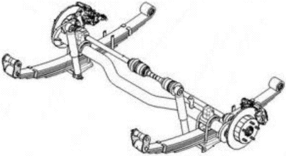
technical field [0001] The invention belongs to the field of automobiles, and in particular relates to a multi-link independent suspension for a drive axle of a commercial vehicle. Background technique [0002] At present, domestic commercial vehicle drive axles mostly adopt integral bridge and leaf spring independent suspension structure. The structure diagram is as follows: figure 1 As shown, its safety, stability, comfort are poor, the weight is large, and the fuel economy is poor. Nowadays, the road conditions of commercial vehicles are getting better and better, the road surface is relatively flat, and the load capacity is relatively large, so the range of motion of the suspension is not large, but there are high requirements for comfort and load capacity. With the needs of industry development and the electrification of commercial vehicles According to the trend, more and more commercial vehicle drive axles will be converted to independent suspension. [0003] In the...

Claims


Application Information

Patent Timeline
Patent Type & Authority Applications(China)
IPC IPC(8): B60G3/20B60G21/055B60G11/00B60G13/00B62D21/02
CPCB60G3/20B60G11/00B60G13/001B60G21/055B60G2204/10B60G2206/011B62D21/02
Inventor 田韶鹏彭浩昆
Owner WUHAN UNIV OF TECH
Learn More