Series-parallel movable heavy load casting robot

A robot and hybrid technology, applied in the direction of casting equipment, manipulators, manufacturing tools, etc., can solve the problems of low load capacity, casting defects, poor working environment, etc.

Active Publication Date: 2017-10-13
ANHUI UNIV OF SCI & TECH
View PDF19 Cites 23 Cited by
  • Summary
  • Abstract
  • Description
  • Claims
  • Application Information

AI Technical Summary

Problems solved by technology

This method has the following disadvantages: (1) The size (weight) of the casting is limited due to the influence of the worker's one-time load. One casting must be poured in a short time. If two or more packages are used Molten iron or molten steel pouring, due to the slow speed of the workers, the castings that are poured out are prone to quality problems such as casting defects; (2) The labor inten

Method used


Image

  • Series-parallel movable heavy load casting robot
  • Series-parallel movable heavy load casting robot
  • Series-parallel movable heavy load casting robot

Examples


specific Embodiment approach 1

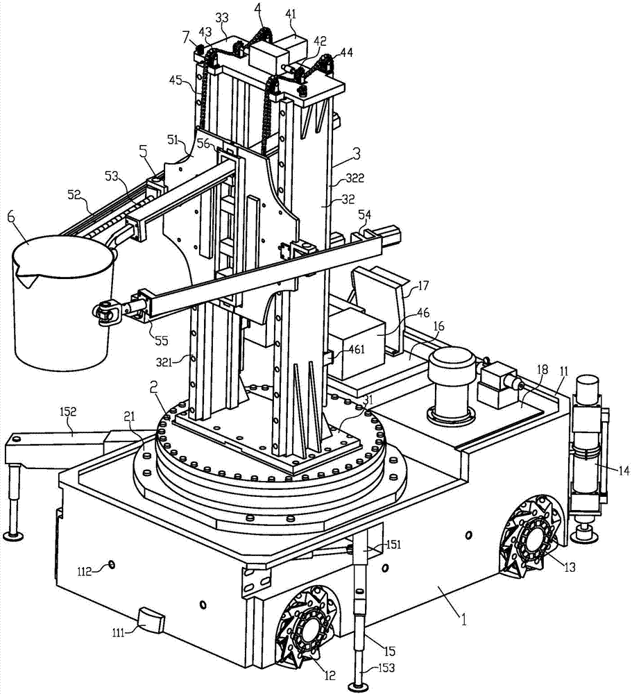
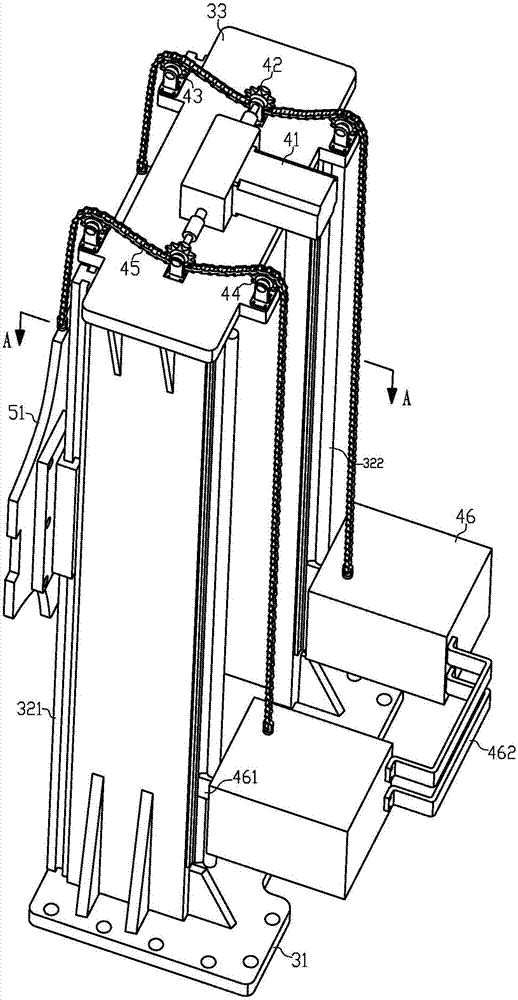
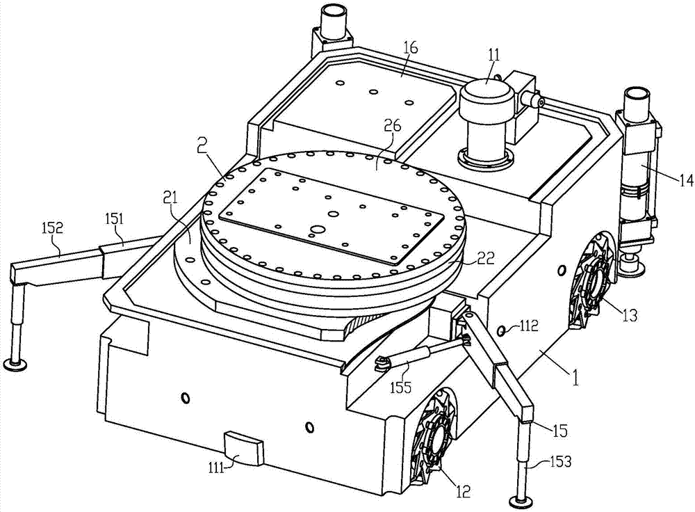
[0032] Such as figure 1 , figure 2 , image 3 , Figure 4 , Figure 7 and Figure 11 As shown, a hybrid mobile heavy-duty casting robot includes a four-wheel-drive wheeled mobile platform 1, a slewing device 2, a column assembly 3, a lifting drive device 4, a parallel working arm 5, an end effector 6 and binocular vision System 7. Wherein, the four-wheel-drive wheeled mobile platform 1 is a bearing and mobile platform of the present invention, comprising a platform frame 11, a front drive wheel 12, a rear drive wheel 13, a rear hydraulic support leg 14, an adjustable hydraulic support leg 15, Controller 16 , monitor 17 and hydraulic pump station 18 . The bottom of the front and rear ends of the platform frame 11 is provided with a navigation sensor 111, and the navigation sensor 111 adopts a magnetic navigation sensor or a laser scanner or an infrared emitter or an ultrasonic transmitter, and is also provided in the platform frame 11. There is a digital biaxial level, ...

specific Embodiment approach 2

[0038] Such as figure 1 , Figure 7 , Figure 8 , Figure 9 and Figure 11 As shown, the first branch chain 52 includes a first front universal joint 521 , a first telescopic group 522 and a first rear hinge 523 . Wherein, the inner end of the first rear hinge 523 is fixedly connected with the working arm mounting base 51, the rear end of the first telescopic group 522 is connected with the outer end of the first rear hinge 523 through a sliding pair, The front end of the first telescopic group 522 is fixedly connected with the rear end of the first front universal joint 521 , and the front end of the first front universal joint 521 is fixedly connected with the end effector 6 . The second branch chain 53 includes a first front hinge 531 , a second telescopic group 532 , a second rear hinge 533 and a first vertical hinge 534 . Wherein, the front end of the first front hinge 531 is fixedly connected to the end effector 6, the front end of the second telescopic group 532 is...

specific Embodiment approach 3

[0041] Such as figure 1 , Figure 10 and Figure 11 As shown, the end effector 6 specifically adopts a multi-finger asynchronous pneumatic gripper, and the multi-finger asynchronous pneumatic gripper includes an air gripper connecting seat 6-1, a connecting bracket 6-2, and an air gripper mounting plate 6-3, jaw finger 6-4 and finger cylinder 6-5. Wherein, the air claw connecting seat 6-1 is fixedly installed on the front end of the parallel working arm 5; the upper end of the connecting bracket 6-2 is fixedly connected with the air claw connecting seat 6-1, and the lower end of the connecting bracket 6-2 It is fixedly connected with the top of the air claw mounting plate 6-3, and a reinforcing connecting rod 6-21 is also provided in the middle of the connecting bracket 6-2; a guide sleeve 6 is provided at the bottom of the air claw mounting plate 6-3 -31, anti-slip rubber 6-41 is provided on the inside of the lower end of the jaw finger 6-4, and a guide rod 6-42 is provide...


PUM


Abstract

The invention discloses a series-parallel movable heavy load casting robot. The series-parallel movable heavy load casting robot comprises a four-wheel drive type moving platform, a rotation device, a stand column assembly, a lifting drive device, a parallel work arm, a tail end executor and a binocular visual system. Four-wheel omnidirectional wheel drive is adopted in the four-wheel drive type moving platform to achieve long-distance flexible stable walking, a rear hydraulic supporting leg and an adjustable hydraulic supporting leg are used for achieving stagnation point self-balance support, work supporting stability is improved, a robot body has five space motion freedom degrees, the rotation device and the lifting drive device can achieve rotation and lifting adjustment, the four-freedom-degree parallel work arm can carry out posture adjustment on the tail end executor, different tail end executors can be replaced according to work needs, different work needs of core assembling, core discharging, casting, carrying and the like of a large casting can be met, the casting core assembling and discharging and casting work efficiency, quality and safety can be improved, and labor intensity and production cost of operators can be reduced.

Description

technical field [0001] The invention belongs to the technical field of foundry robot equipment, in particular to a hybrid mobile heavy-duty foundry robot. Background technique [0002] The high flexibility of industrial robots can meet various special requirements in modern green casting production. The use of robots in casting production can not only liberate operators from heavy and monotonous physical labor, save labor, but also improve casting production efficiency, It is an important means of manufacturing precision and quality, and realizing the mechanization, automation and civilization of casting production. At present, adopting advanced and applicable new foundry technologies to improve the automation level of foundry equipment, especially the application of mobile robot technology, is a key measure for foundry enterprises to implement green foundry production and achieve sustainable development. Due to the harsh environment of high temperature, high dust, vibratio...

Claims


Application Information

Patent Timeline
IPC IPC(8): B22D37/00
CPCB22D37/00B25J5/007B25J9/0072B25J19/002B25J9/041B25J15/0293B25J11/005B25J15/0019B25J15/02B25J19/021
Inventor 王成军郭永存任润润沈豫浙郑艳李龙杨洪涛张军王鹏
Owner ANHUI UNIV OF SCI & TECH
Why Eureka
Try Eureka