Carbon Disulfide Gasification Reactor Heating Device and Heating Method

A carbon disulfide, gasification reaction technology, applied in the direction of carbon disulfide, carbon sulfur compounds, etc., can solve the problems of high flue exhaust temperature, short hot gas flow, low heat energy utilization rate, etc., achieve low fuel consumption and reduce flue gas temperature. , the effect of high energy utilization

Active Publication Date: 2019-06-04
阳城县绿色铸造研发中心 +1
View PDF5 Cites 0 Cited by
  • Summary
  • Abstract
  • Description
  • Claims
  • Application Information

AI Technical Summary

Problems solved by technology

[0003] In order to solve the defects of the above-mentioned heating device and heating method, such as short flow of hot gas in the combustion chamber, high exhaust gas temperature in the flue, low heat energy utilization rate, large fuel consumption, and high pollutant discharge, the present invention provides a carbon disulfide gasification reaction furnace Heating device and heating method

Method used


Image

  • Carbon Disulfide Gasification Reactor Heating Device and Heating Method
  • Carbon Disulfide Gasification Reactor Heating Device and Heating Method
  • Carbon Disulfide Gasification Reactor Heating Device and Heating Method

Examples


Embodiment 1

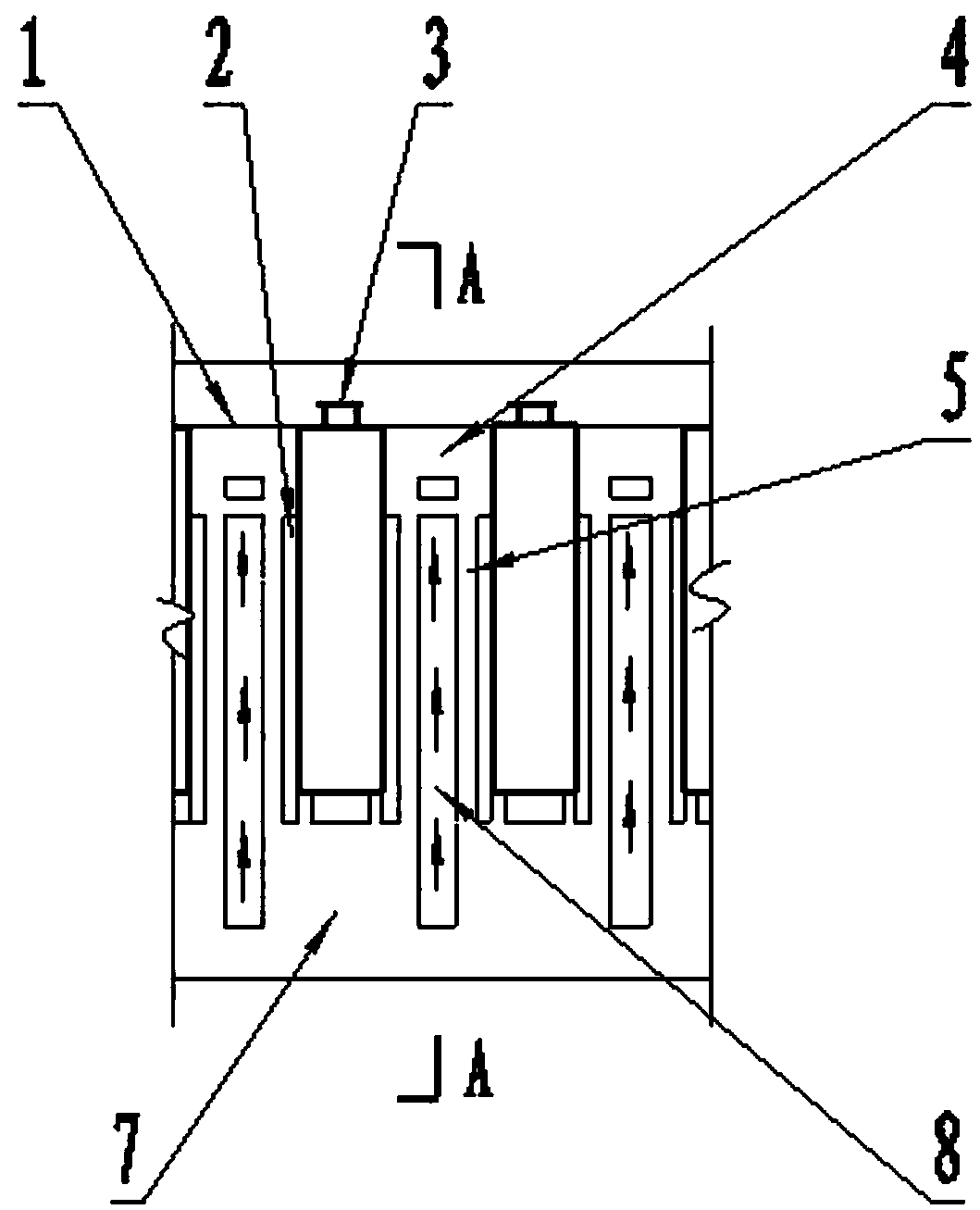
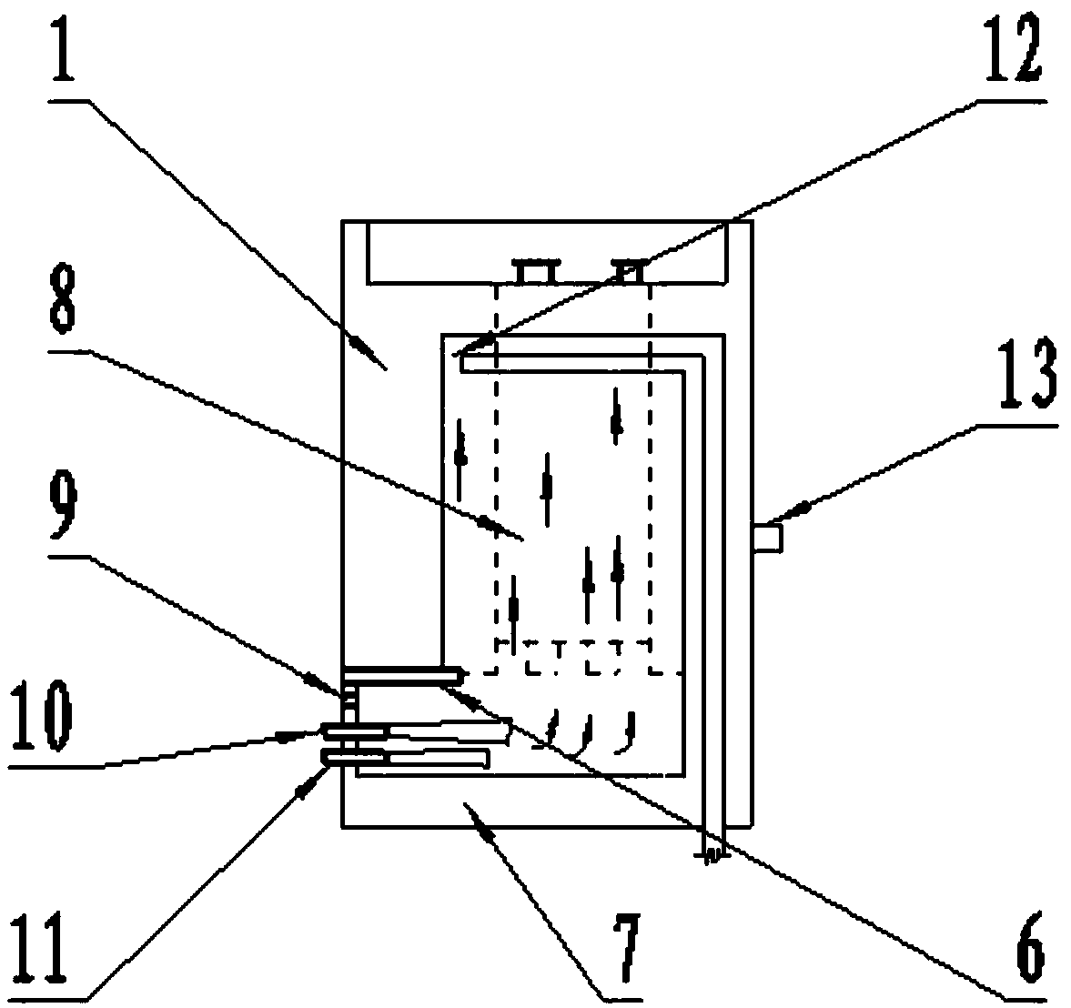
[0024] Such as Figure 3-4 As shown, a carbon disulfide gasification reaction furnace heating device in this embodiment is composed of an external heating furnace 1, a hot air flow radiation channel 2 and a carbon disulfide reaction kettle 3. The hot air radiation channel 2 is arranged between them; the external heating furnace 1 includes a furnace roof 4, a combustion chamber furnace wall 5, a support plate 6, a furnace base 7 and a combustion chamber 8; the furnace roof 4, the combustion chamber furnace wall 5 and the furnace base 7 are fixedly connected by refractory materials; the combustion chamber 8 includes an ignition hole 9, a gas fuel nozzle 10, an air inlet 11, a smoke outlet 12 and a thermometer 13; the ignition hole 9, the gas fuel nozzle 10 and the air inlet 11 are sequentially arranged on the bottom side of the external heating furnace; the support plate 6 is arranged horizontally on the top of the ignition hole 9 and extends into the combustion chamber 8; the s...

Embodiment 2

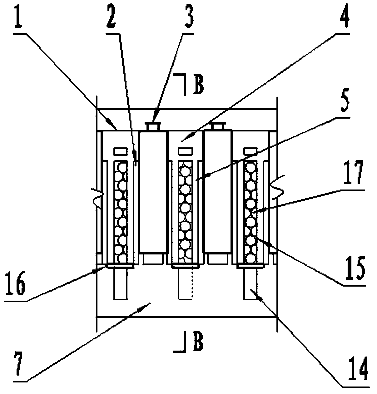
[0027] As shown in 5-6, a carbon disulfide gasification reaction furnace heating device in this embodiment, the checker brick 18 is arranged on the furnace bar 16 and the checker brick 18 is located in the upper heating regenerator 15, and the checker brick 18 vertical layered criss-cross set. The checker brick 18 is made of high alumina refractory material. All the other structures are the same as those in Example 1.

[0028] The heating method of a carbon disulfide gasification reaction furnace heating device in this embodiment is the same as the heating method in Embodiment 1 except that the refractory ball 17 is replaced by checker bricks 18 .

[0029] The coal gas in the above embodiments can also be replaced by coalbed methane or natural gas.

[0030] In the heating method in the above embodiment, after the external heating furnace 1 is turned on for heating, when the temperature in the upper heating regenerator 15 reaches 950°C-1000°C, it is also possible to reduce th...


PUM

PropertyMeasurementUnit
diameteraaaaaaaaaa

Abstract

The invention belongs to the technical field of carbon disulfide production equipment, particularly relates to a carbon disulfide gasification reacting furnace heating device and a heating method, and solves the technical problems of low heat utilization ratio of a combustion chamber, large fuel consumption and more discharge of pollutants in the existing carbon disulfide gasification reacting furnace heating device and the existing heating method. The carbon disulfide gasification reacting furnace heating device comprises an external heating furnace, a hot air flow radiation channel and a carbon disulfide reaction kettle; the combustion chamber comprises a lower combustion chamber and an upper heating and heat storing chamber, and a refractory ball or a checker brick is arranged in the upper heating and heat storing chamber. The heating device adopts a gas fuel in the combustion, and when the refractory ball or the checker brick in the upper heating and heat storing chamber is heated to 950 DEG C to 1000 DEG C, the lower combustion chamber stops combustion, the refractory ball or the checker brick in the upper heating and heat storing chamber starts to release heat, and the materials in the reaction kettle are continuously supported to have the chemical reaction. The fuel consumption is low, the energy utilization rate is high, the discharge of pollutants is little, and the obvious effects of saving energies and reducing emissions are achieved.

Description

technical field [0001] The invention belongs to the technical field of carbon disulfide production equipment, and in particular relates to a heating device and a heating method for a carbon disulfide gasification reaction furnace. Background technique [0002] The production of carbon disulfide by the coke method is a well-known technology, the core process of which is the chemical reaction between coke and sulfur in a reactor at a temperature of 800°C to 900°C to generate carbon disulfide. At present, the heating device and method to support its chemical reaction is that raw coal, coke or gas fuel is burned in the combustion chamber of the external heating furnace to generate heat, and the heat is radiated through the furnace wall of the combustion chamber and the hot air flow between the furnace wall of the combustion chamber and the gasification reactor. And the wall of the gasification reactor is conducted to the reaction material in the gasification reactor. Since the ...

Claims


Application Information

Patent Timeline
Patent Type & Authority Patents(China)
IPC IPC(8): C01B32/72
Inventor 薛媛王录才田晋平田新社高修启孙家聚崔海平
Owner 阳城县绿色铸造研发中心
Why Eureka
Try Eureka