Automatic control switch valve and process method thereof

A process method and technology for switching valves, applied in the hydraulic field, can solve the problems of hydraulic shock, difficult processing, and high valve precision requirements, and achieve the effects of small hydraulic shock, easy processing and manufacturing, and stable processing dimensions.

Inactive Publication Date: 2017-10-13
GUANGDONG TINGJIA HYDRAULIC TECH CO LTD
View PDF6 Cites 2 Cited by
  • Summary
  • Abstract
  • Description
  • Claims
  • Application Information

AI Technical Summary

Problems solved by technology

[0002] At present, hydraulic valves such as sequence valves, priority valves, and filling valves in the hydraulic system need to control two hydraulic circuits with different pressures and flows, especially the clamping hydraulic circuit system that requires pressure maintenance and has an accumulator. The control part of the hydraulic valve is relatively complicated, the precision of the valve is high, the processing is difficult, and the size of the key parts is difficult to control, resulting in unstable dynamic performance of key core components and easy hydraulic shock of the system

Method used


Image

  • Automatic control switch valve and process method thereof
  • Automatic control switch valve and process method thereof
  • Automatic control switch valve and process method thereof

Examples


Embodiment 1

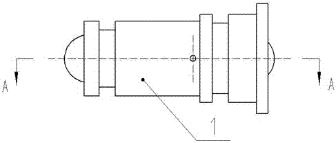
[0019] Embodiment 1, an automatic control switching valve, including a switching valve body, a switching valve core, a left steel ball, and a right steel ball, the switching valve core is installed in the valve hole of the switching valve body, and the left steel ball is installed in the switching valve body The left side and the right steel ball are installed on the right side of the switching valve body. The center of the switching valve body is designed with a straight-through valve hole, the left side of the switching valve body is designed with a large-angle sealing cone surface, the right side of the switching valve body is designed with a small-angle sealing cone surface, and the switching valve body is designed with a damping hole. There are two O-ring grooves. The switching spool is designed as a slide valve spool with a large middle and small ends.

Embodiment 2

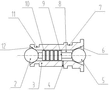
[0020] Embodiment 2, with reference to Figure 1 to Figure 4 As shown, an automatic control switching valve includes a switching valve body, a switching valve core, a first steel ball, and a second steel ball. The switching valve body (3) is processed with a straight-through valve hole (8). The right side of the switching valve body (3) is processed with a small-angle sealing cone surface (6), the left side of the switching valve body (3) is processing a large-angle sealing cone surface (12), and the switching valve body (3) is The damping hole (4) is processed on the top, and the switching valve body is provided with a first O-ring groove (7) and a second O-ring groove (11) on both sides of the damping hole (4); the switching The spool (9) is installed in the valve hole (8) of the switching valve body (3); the first steel ball (2) is installed on the left side of the switching valve body (3); the second steel ball (5) Installed on the right side of the switching valve body (...

Embodiment 3

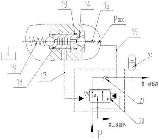
[0021] Embodiment 3, the oil outlet of the hydraulic pump is connected to the oil port P to supply oil to the hydraulic system. When the control pressure Pacc of the first control oil passage (16) is lower than the set lower limit pressure value Pd, it acts on the second steel ball (5) The hydraulic pressure F5 (F5=Pd*S5) and the spring force F15 of the return spring (15) are smaller than the spring force F19 of the pressure regulating spring (19), and the spring force F19 of the pressure regulating spring (19) passes the first The steel ball (2) and the switching spool (9) force the second steel ball (5) to leave the small-angle sealing cone (6) on the right side of the switching valve body (3), and the second steel ball (5) and the small-angle sealing The conical surface (6) forms a gap (14), the hydraulic oil of the first stage circuit enters the right side of the switching valve (1) through the first control oil passage (16), and passes through the second gap (14), the valv...


PUM


Abstract

The invention discloses an automatic control switch valve and a process method thereof. The automatic control switch valve is characterized in that a switch valve element is installed in a valve hole of a switch valve body; a first steel ball is installed on the left side of the switch valve body; a second steel ball is installed on the right side of the switch valve body; a straight through valve hole is formed in the switch valve body; a small-angle sealing cone face is designed on the right side of the switch valve body; a large-angle sealing cone face is designed on the left side of the switch valve body; a damping hole is designed in the switch valve body; the switch valve body is provided with a first O-shaped ring groove and a second O-shaped ring groove which are located in the two sides of the damping hole; and the switch valve element is designed into a sliding valve element with the large middle and the two small ends. The automatic control switch valve can be arranged in a sequence valve, a priority valve and a liquid charging valve in a plug-in mounting manner, and has the beneficial effects of being simple in structure, easy to machine and manufacture, stable in machining size, reliable in action, small in hydraulic impacting of a system and the like.

Description

technical field [0001] The invention belongs to the field of hydraulic pressure, and in particular relates to an automatic control switching valve and a process method thereof. Background technique [0002] At present, hydraulic valves such as sequence valves, priority valves, and filling valves in the hydraulic system need to control two hydraulic circuits with different pressures and flows, especially the clamping hydraulic circuit system that requires pressure maintenance and has an accumulator. The control part of the hydraulic valve is relatively complicated, the valve has high precision requirements, the processing is difficult, and the size of the key parts is difficult to control, resulting in unstable dynamic performance of key core components and easy hydraulic shock of the system. Comparative document 1, application number: CN200520109691, invention name: high and low pressure switching valve, its structure is that a valve core is installed in the valve body, and ...

Claims


Application Information

Patent Timeline
Patent Type & Authority Applications(China)
IPC IPC(8): F15B13/02F15B21/00
CPCF15B13/02F15B21/001F15B2211/3056F15B2211/315
Inventor 蒙学刘
Owner GUANGDONG TINGJIA HYDRAULIC TECH CO LTD
Why Eureka
Try Eureka