
Lithium ion battery

A lithium-ion battery and separator technology, applied in the field of lithium-ion batteries, can solve the problems of insufficient welding stability of multi-pole lugs, fluctuations in coating surface density, fluctuations in battery internal resistance, etc. The effect of maximizing the current passing area and minimizing the current path

Pending Publication Date: 2017-10-13
衡阳力赛储能有限公司
View PDF7 Cites 3 Cited by
  • Summary
  • Abstract
  • Description
  • Claims
  • Application Information

AI Technical Summary

Problems solved by technology

[0005] 1. During the production process of traditional battery pole pieces, it is necessary to consider the reservation of the welding position between the tab and the pole piece, which requires intermittent coating on the current collector. Intermittent coating of the pole piece will reduce the coating speed, which is not conducive to the release of production capacity; In addition, the scraping method after continuous coating also faces the problems of low production efficiency, secondary pollution of pole pieces and insulation of tabs
[0006] 2. Intermittent coating will cause fluctuations in coating surface density and increase the risk of battery capacity differentiation
[0007] 3. There is a risk of insufficient stability in multi-pole welding, which may easily cause fluctuations in the internal resistance of the battery
[0008] However, the single lug design of the positive and negative electrodes is not conducive to the realization of high power output or input of the battery; the multi-lug design has problems such as difficulty in aligning the tabs, difficulty in insulating the tabs, and the multi-lug battery core tends to be elliptical.

Method used


Image

  • Lithium ion battery
  • Lithium ion battery
  • Lithium ion battery

Examples


Embodiment Construction

[0047]In the description of the present invention, it should be understood that the orientations or positional relationships indicated by the terms "upper", "lower", "top", "bottom", "inner", "outer" etc. are based on those shown in the accompanying drawings. Orientation or positional relationship is only for the convenience of describing the present invention and simplifying the description, and does not indicate or imply that the referred device or element must have a specific orientation, be constructed and operated in a specific orientation, and thus should not be construed as a limitation of the present invention.

[0048] In order to facilitate those skilled in the art to better understand the improvements of the present invention over the prior art, the present invention will be further described below in conjunction with specific embodiments and accompanying drawings.

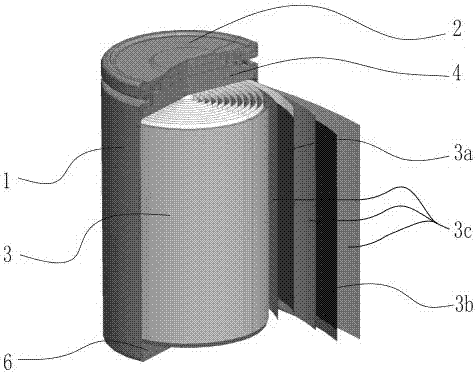
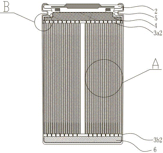
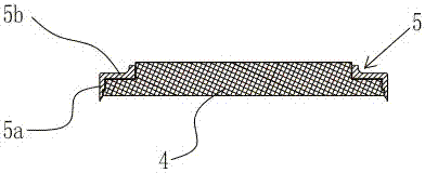
[0049] Figure 1-10 The specific structure of the lithium-ion battery involved in the present invent...


PUM

PropertyMeasurementUnit
Thicknessaaaaaaaaaa
Wall thicknessaaaaaaaaaa
Diameteraaaaaaaaaa

Abstract

The invention discloses a lithium ion battery, and relates to the technical field of battery energy storage. The lithium ion battery comprises a metal shell, a cover plate and a columnar roll core arranged in the metal shell; the columnar roll core comprises a positive electrode plate, a negative electrode plate and an isolation membrane; the positive electrode plate comprises a positive electrode paste coating region and a positive electrode current collector exposure region; the negative electrode plate comprises a negative electrode paste coating region and a negative electrode current collector exposure region; the overlaid parts of the positive electrode plate and the negative electrode plate are isolated through the isolation membrane; the width of the isolation membrane is less than the height of the columnar roll core; a positive electrode confluence plate and an insulating confluence plate fixing frame are arranged below the cover plate; the confluence plate fixing frame comprises a side edge insulating part which is sleeved outside the positive electrode confluence plate and the exposed positive electrode current collector; and after the lithium ion battery is assembled, the parts tightly prop against together through extrusion force, so that physical switch-on can be realized through a non-welding manner. The lithium ion battery does not comprise a tab as the conventional battery, and the interior of the cell has no welding point, so that the battery is high in consistency and high high-rate charging and discharging performance and battery energy density can be obtained.

Description

technical field [0001] The invention relates to the technical field of battery energy storage, in particular to a lithium ion battery. Background technique [0002] With the development of mobile electrical equipment and energy storage products, secondary lithium batteries are gradually recognized by the market as a representative of high-energy-density batteries. The common shapes of lithium-ion batteries are mainly cylindrical and square. [0003] The internal structure of the traditional cylindrical secondary lithium battery is as follows: firstly, the winding core is made, and the winding core is formed by winding a layer of positive electrode sheet, a layer of separator, a layer of negative electrode sheet, and a layer of separator film, and the positive electrode sheet and the negative electrode sheet Both include a current collector made of conductive material (the current collector of the positive pole is called the positive current collector, and the current collect...

Claims


Application Information

Patent Timeline
IPC IPC(8): H01M10/0587H01M10/052H01M4/70
CPCH01M4/70H01M10/052H01M10/0587Y02E60/10Y02P70/50
Inventor 陈建军文利
Owner 衡阳力赛储能有限公司
Learn More