Spraying type road dedusting and cleaning system

A cleaning system and spray-type technology, applied in the direction of spray device, spray device, dispersed particle separation, etc., can solve the problems of influence, inability to achieve air dust removal, road cleaning effect, inconvenience, etc., and achieve good breathing experience and good cleaning effect. , the effect of dense distribution

Inactive Publication Date: 2017-10-20
刘明谭
View PDF7 Cites 2 Cited by
  • Summary
  • Abstract
  • Description
  • Claims
  • Application Information

AI Technical Summary

Problems solved by technology

However, various sulfur oxides, nitrogen oxides and other waste smoke, waste gas, waste water, and waste residues emitted by industries and automobiles are becoming more and more serious. Many pollutants float on the road or in the air, and some suburban roads often pass large-scale Freight vehicles, the air and the road are covered with dust, and the breathing of pedestrians will be extremely unbearable. Originally, rainfall activities can effectively wash away suspended solids and dust, and can take away various particle types of pollution on the road surface, but only Relying on rainfall can't achieve the effect of air dust removal and road surface cleaning at all, and the high-pressure water sprayed by traditional urban cleaning vehicles will cause great inconvenience to passers-by on the road. Splash pedestrians all over their bodies, causing bad influence
For this reason, there is a need for a device that can effectively clean up the dust and suspended matter in the air and on the road surface, and can not affect the pedestrians on the road while cleaning, but the traditional cleaning equipment in the prior art cannot meet the above requirements

Method used


Image

  • Spraying type road dedusting and cleaning system
  • Spraying type road dedusting and cleaning system
  • Spraying type road dedusting and cleaning system

Examples


Embodiment Construction

[0021] The present invention will be described in detail below in conjunction with specific embodiments. This embodiment provides detailed implementation methods and specific operation processes on the premise of the technical solution of the present invention.

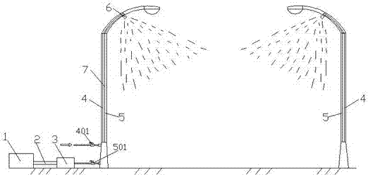
[0022] As shown in the figure, the present invention is a spray-type road dust removal and cleaning system. The system includes an air compressor 1, an air storage tank 3 connected to the air compressor 1 through a compressed air pipe 2, a water pipe 4 arranged side by side and an air Road pipeline 5 and the atomizing nozzle 6 connected at the outlet of water pipeline 4 and gas pipeline 5, wherein, the water pipeline 4 and gas pipeline 5 are all hidden in the street lamp poles 7 on both sides of the road, and the street lamp poles 7 The bottom end is provided with a water valve 401 and an air valve 501 respectively communicated with the water pipeline 4 and the air pipeline 5, the water valve 401 is connected to an ext...


PUM


Abstract

A spraying type road dedusting and cleaning system comprises an air compressor, an air storage tank connected with the air compressor through a compressed air pipeline, waterway pipelines and air passage pipelines which are arranged side by side, and atomization nozzles connected between the outlets of the waterway pipelines and the outlets of the air passage pipelines, wherein the waterway pipelines and the air passage pipelines are hidden in street lamp rack rods at two sides of a road, the bottom ends of the street lamp rack rods are respectively provided with water valve communicating with the waterway pipelines and air valves communicating with the gas passage pipelines, the water valves are connected with an external water source to convey water to the waterway pipelines, the air valves communicate with the air storage tank to convey air to the gas passage pipelines through the air compressor, and the atomization nozzles are arranged in positions, close of to street lamps, at the tops of the street lamp rack rods. The system utilizes the existing street lamp rack rods at two sides of the road, reduces the cleaning cost, and avoids the influences of the road cleaning process on pedestrians because people have no feeling when water mist having very small particle size and sprayed by the atomization nozzles sprinkles on people's skins.

Description

technical field [0001] The invention relates to the technical field of road cleaning equipment, in particular to a spray-type road dust removal and cleaning system. Background technique [0002] With the continuous advancement of science and technology and the continuous development of society, more and more work in urban sanitation and cleaning has been completed by highly automated equipment, replacing traditional human labor and improving work efficiency to a certain extent. It also cleans better. For urban roads, the existing cleaning vehicles mainly use the sweeping disc to clean the road surface, and then use the cleaning vehicle to clean the urban road surface with high-pressure water to complete the cleaning and cleaning of urban roads. The cleaning vehicle technology can effectively clean the urban road surface. However, various sulfur oxides, nitrogen oxides and other waste smoke, waste gas, waste water, and waste residues emitted by industries and automobiles ar...

Claims


Application Information

Patent Timeline
Patent Type & Authority Applications(China)
IPC IPC(8): B01D47/06B05B1/00
CPCB01D47/06B05B1/00
Inventor 刘明谭朱同功刘国政李建功郭铁成郭东强赵晓兵高要昌李东佳李永超
Owner 刘明谭
Why Eureka
Try Eureka