Supercharge Your Innovation With Domain-Expert AI Agents!

High-stability ultrasonic air floating electric spindle

A high-stability, ultrasonic technology, used in large fixed members, metal processing machinery parts, metal processing equipment, etc., can solve the problem of affecting the life of components and grinding quality, the fluidity of coolant cannot be guaranteed, and the heat of the electric spindle cannot be evacuated. and other problems, to achieve the effect of improving quality, stable rotation and effective cooling effect

Pending Publication Date: 2017-10-20
东莞市科隆实业有限公司
View PDF7 Cites 3 Cited by
  • Summary
  • Abstract
  • Description
  • Claims
  • Application Information

AI Technical Summary

Problems solved by technology

Since the electric spindle needs a lot of friction to generate heat during operation, its cooling has become one of the key problems to be solved. The use of existing coolants has a small contact surface with the spindle, and the fluidity of the coolant cannot be guaranteed. At the same time, the axis The front and rear bearings are required for positioning, but the positioning is still not stable enough, and there will be insufficient contact when it is matched with the coolant, causing the coil of the electric spindle to generate a large amount of heat during operation and cannot be evacuated. The effect of the coil on heat dissipation remains to be seen. improve
At the same time, the dust generated during work will be attached to the electric spindle, which will affect the life of the components and the grinding quality

Method used


Image

  • High-stability ultrasonic air floating electric spindle
  • High-stability ultrasonic air floating electric spindle
  • High-stability ultrasonic air floating electric spindle

Examples


Embodiment Construction

[0020] The present invention will be further described below in conjunction with accompanying drawing:

[0021] The directional terms mentioned in the following embodiments, such as "up, down, left, right" are only referring to the directions of the drawings, therefore, the directional terms are used for illustration and not for limiting the present invention.

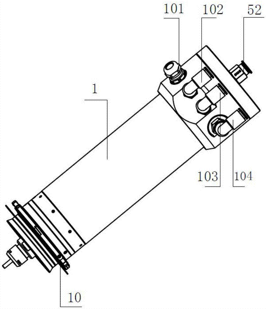
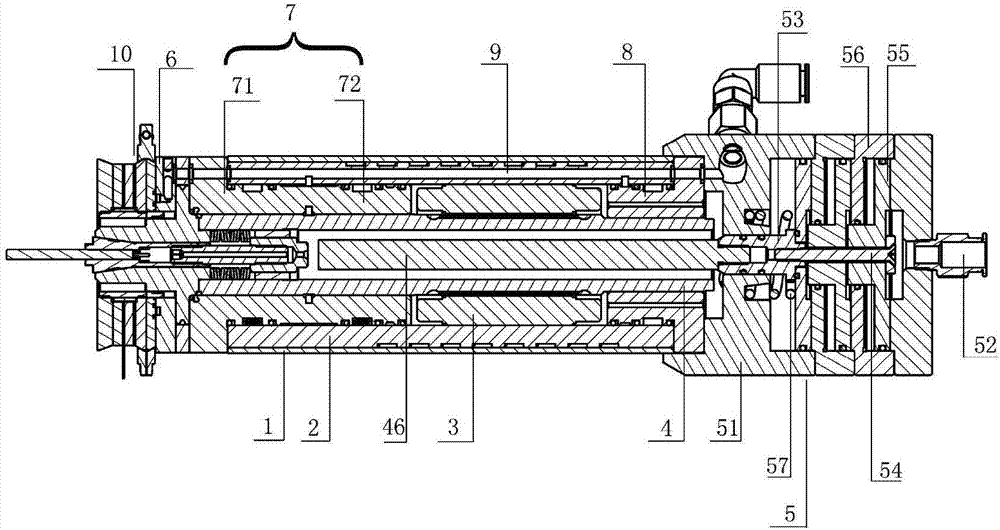
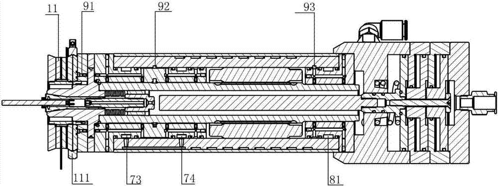
[0022] Such as Figure 1-8 As shown, the high-stability ultrasonic air-floating electric spindle includes the motor spindle body 1, the body liner 2, the stator 3 and the shaft core 4 from the outside to the inside in turn, and the tail of the shaft core is connected to the motor assembly 5; The multi-section bearing provided between the shaft core and the main shaft body 1, the bearing includes a push bearing 6 arranged at the shaft head of the front end of the shaft core 4, the rear end of the shaft core 4 and the stator 3 The rear bearing 8 arranged between and the middle bearing 7 arranged between the front part o...


PUM


Abstract

The invention provides a high-stability ultrasonic air floating electric spindle. The high-stability ultrasonic air floating electric spindle sequentially comprises a body inner container, a spindle body, a stator and a shaft core from outside to inside. The tail of the shaft core is connected with a motor assembly. Multiple sections of bearings are arranged between the shaft core and the spindle body. The bearings comprise the push bearing arranged on the shaft head at the front end of the shaft core, the rear bearing arranged between the rear end of the shaft core and the stator and the middle bearing arranged between the middle front portion of the shaft core and the stator. The middle bearing comprises a front portion and a rear portion. A hoop and an ultrasonic transducer assembly which are fixed with each other are further arranged on the outer surface of the front end of the spindle body. According to the high-stability ultrasonic air floating electric spindle, the multiple bearings are designed on the spindle body, the middle bearing can cooperate with the bearings in front of and behind the middle bearing in the shaft core rotating process, and rotation of a rotary shaft is more stable; cooling liquid passes through a cooling through groove and cooperates with multiple air ways, and the obvious slow-down function on reducing of coil heating is achieved; and an ultrasonic transducer is arranged on the electric spindle, dust can be effectively removed, a grinding head can keep clean, the grinding quality can be improved, and the service life of a component can be prolonged.

Description

technical field [0001] The invention relates to the field of motor shafts, in particular to a high-stable electric spindle structure using ultrasonic waves. Background technique [0002] With the rapid development and improvement of electric drive technology (frequency conversion speed regulation technology, motor vector control technology, etc.), the mechanical structure of the main drive system of high-speed CNC machine tools has been greatly simplified, and the pulley drive and gear drive have been basically eliminated. . The main shaft of the machine tool is directly driven by the built-in motor, thus shortening the length of the main transmission chain of the machine tool to zero, and realizing the "zero transmission" of the machine tool. This type of transmission structure in which the spindle motor and the machine tool spindle are "integrated into one" makes the spindle components relatively independent from the transmission system and the overall structure of the ma...

Claims


Application Information

Patent Timeline
IPC IPC(8): B23B19/02
CPCB23Q1/70
Inventor 陈文泉
Owner 东莞市科隆实业有限公司
Features
  • R&D
  • Intellectual Property
  • Life Sciences
  • Materials
  • Tech Scout
  • Unparalleled Data Quality
  • Higher Quality Content
  • 60% Fewer Hallucinations
Learn More