
Wallboard forming device of load bearing wall

A wallboard molding and load-bearing wall technology, applied in auxiliary molding equipment, ceramic molding machines, ceramic molding workshops, etc., can solve the problems of heavy material weight, difficulty in meeting multi-functional quality requirements, and low strength

Inactive Publication Date: 2017-10-20
安阳三乔环保科技有限公司
View PDF18 Cites 2 Cited by
  • Summary
  • Abstract
  • Description
  • Claims
  • Application Information

AI Technical Summary

Problems solved by technology

Especially in recent years, with the high development of the real estate industry, in order to maximize the benefits on the limited land area, high-rise buildings are an effective way. In addition, shortening the circulation of funds and realizing profits in the shortest time has become The development trend in the field of real estate. At present, there are two major trends in the development of prefabricated panels. One is to use extrusion molding. This molding method has the characteristics of fast molding speed and good strength, but this material is heavy and has a single function. It is difficult to meet the multi-functional quality requirements. Another manufacturing method is infusion molding, which is mainly formed by foaming. It has light weight and sound insulation effect, but low strength. The wall panels manufactured by the above two manufacturing methods are used in construction. How to manufacture the prefabricated panels set in the building frame, how to manufacture the load-bearing wall prefabricated panels with high strength, relatively light weight and thermal insulation effect, will further shorten the construction period, achieve real estate sales as soon as possible, and withdraw funds as soon as possible. A consensus that prefabrication of load-bearing wall panels is an effective way to further shorten the construction period

Method used


Image

  • Wallboard forming device of load bearing wall
  • Wallboard forming device of load bearing wall
  • Wallboard forming device of load bearing wall

Examples


Embodiment Construction

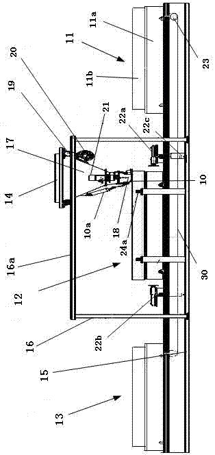
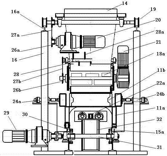
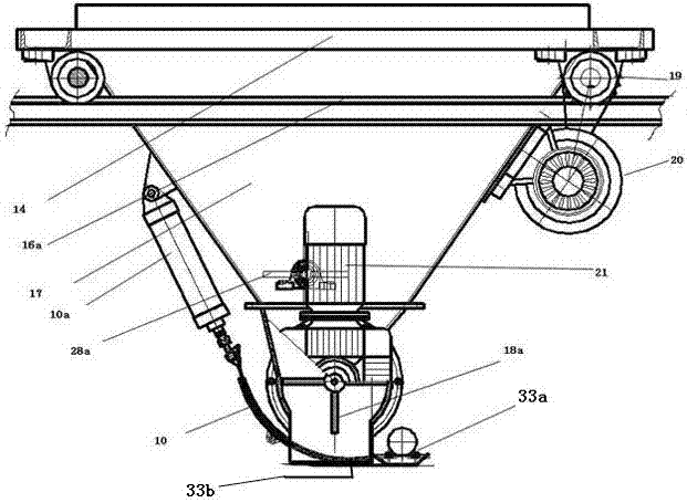
[0019] The technical solution of the present invention will be described in detail below with reference to the accompanying drawings. In the description, the moving direction of the board-making mold is taken as the front-rear direction, and the direction perpendicular to the front-rear direction on a horizontal plane is used as the left-right direction for illustration.

[0020] Explanation of symbols: 10-distributor door, 10a-door opening cylinder, 11-preparation station, 11a-formwork car, 11b-board making mold, 12-board making station, 13-finished product station, 14-hopper car , 15-lower frame, 15a-lower guide rail, 16-upper frame, 16a-upper guide rail, 17-hopper, 18-distributor, 18a-pulling plate, 19-hopper car wheel, 20-hopper car deceleration motor , 21-cloth deceleration motor, 22a-inlet side end push cylinder, 22b outlet side end push cylinder, 22c-lift cylinder, 23-drag chain sprocket, 24a-left side clamp cylinder, 24b-right side side clamp cylinder, 26a-Driving spro...


PUM


Abstract

The invention relates to a wallboard forming device of a load bearing wall, and belongs to the field of construction equipment. The wallboard forming device comprises a plurality of stations including board-making stations, and a die set car is arranged every two adjacent stations, and provided with a board-making mould in which steel bars and mold cores are preinstalled; and hopper cars are arranged above the board-making stations, and each hopper car comprises a hopper below which a distributing device is arranged. By adopting the wallboard forming device provided by the invention, prefabricated parts are arranged internally and compounding materials are cast according to the customer requirements; wallboards made of required materials can be installed in buildings directly after being fabricated in a board mill in advance, and the prefabricated boards with the advantages of high strength, light weight and high temperature resistance can be manufactured in a repeated overlapping manner, so that the engineering construction speed is improved to facilitate enterprises to recoup funds and increase velocity of capital turnover, and the economic benefits are improved.

Description

technical field [0001] The invention relates to a forming device, in particular to a load-bearing wall panel forming device, which belongs to the field of construction equipment. Background technique [0002] Traditional building walls are generally formed by stacking or fixing bricks, plates and other materials. With the development of science and technology, new requirements are put forward for building methods and building structures. In the construction industry, in order to improve the quality of buildings, walls The body generally adopts fast building speed, light weight, non-polluting green environmental protection, sound insulation, flame retardant and other materials, and the wall body is prefabricated in advance to achieve efficient and fast construction. Especially in recent years, with the high development of the real estate industry, in order to maximize the benefits on the limited land area, high-rise buildings are an effective way. In addition, shortening the ...

Claims


Application Information

Patent Timeline
IPC IPC(8): B28B15/00B28B13/02B28B17/00B28B23/02
CPCB28B13/025B28B15/00B28B17/00B28B17/0081B28B23/02
Inventor 乔红卫曲双保
Owner 安阳三乔环保科技有限公司
Learn More