Supercharge Your Innovation With Domain-Expert AI Agents!

Using method of automatic water drainage system for hydraulic engineering construction

An automatic drainage and water conservancy engineering technology, applied in water conservancy engineering, water conservancy engineering equipment, marine engineering and other directions, can solve the problems of difficult construction, waste of water resources, affecting the safety of the lock body, etc., to reduce water resources loss, simple structure, Easy to install effect

Active Publication Date: 2017-10-20
桐城市建设投资发展有限责任公司
View PDF5 Cites 0 Cited by
  • Summary
  • Abstract
  • Description
  • Claims
  • Application Information

AI Technical Summary

Problems solved by technology

[0002] In the construction of water conservancy projects, construction is often carried out in places lower than the water level, so that the project site will cause water accumulation due to water seepage or leakage, which will affect the construction of dry land; for example, large and medium-sized sluices for drainage are equipped with stilling pools The stilling pool is an important part of the sluice. Whether its structure is stable or not directly affects the safety of the sluice body, which in turn threatens the personal and property safety of the people downstream. Since the stilling pool has been subjected to hydraulic erosion for a long time, after a certain period of time, The bottom surface of the stilling tank is numb and shows tendons. In the past, when the condition of the stilling tank was maintained, the upstream water storage was mostly emptied to reduce the water seepage intensity and volume of the stilling tank, and then the whole stilling tank was demolished and rebuilt. Water storage will cause a huge waste of water resources, and if the stilling tank is not released, water will seep upward because the stilling tank is located in a low-lying place, so it is very difficult to construct during the initial construction or maintenance and reinforcement

Method used


Image

  • Using method of automatic water drainage system for hydraulic engineering construction
  • Using method of automatic water drainage system for hydraulic engineering construction
  • Using method of automatic water drainage system for hydraulic engineering construction

Examples


Embodiment

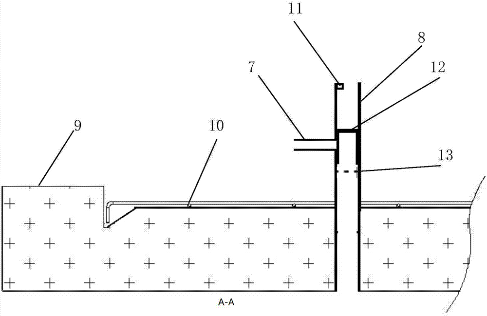
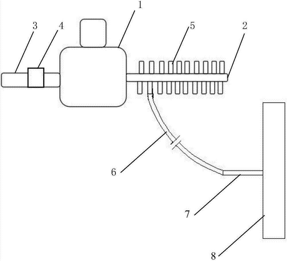
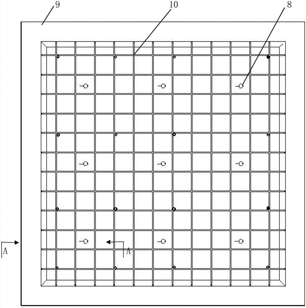
[0026] Embodiment, with reference to accompanying drawing: a kind of automatic drainage system for water conservancy project construction, comprises water pump 1 and water collecting pipe 8, described water pump 1 is provided with PLC control board and water inlet pipe 2, water outlet pipe 3, described PLC control board A wireless receiving module is provided, and the water inlet pipe 2 is provided with a plurality of sub-water inlet pipes 5, and the sub-water inlet pipes 5 are respectively connected to the water suction pipes 6, and each water suction pipe 6 is connected to the water suction joint 7 of the corresponding water collection pipe 8. The water collecting pipe 8 is arranged at the seepage place.

[0027] Further, the water collecting pipe 8 is vertically arranged, and a horizontal water pumping joint 7 is provided in the middle, and the water pumping joint 7 is connected with the water pumping pipe 6. A grid 13 is arranged under the inner hole of the water collecting...


PUM


Abstract

The invention relates to a using method of an automatic water drainage system for hydraulic engineering construction. The automatic water drainage system comprises a water pump and water collecting pipes. The water pump is provided with a PLC control panel, a water inlet pipe and a water outlet pipe. The PLC control panel is provided with a wireless receiving module. The water inlet pipe is provided with a plurality of branch water inlet pipes. The branch water inlet pipes are connected with water pumping pipes. The water pumping pipes are connected to the corresponding water collecting pipes. The water collecting pipes are arranged in water seepage positions. Each water collecting pipe is internally provided with a grid and a floating body, an inductor is arranged at an upper opening of the water collecting pipe, the floating body ascends to get close to the inductor on the upper portion, the inductor emits a water pump opening signal, a detector located in the water outlet pipe detects that water in the water outlet pipe is stopped or the water flow speed is lower than a set value, the detector emits a water pump closing signal, and accordingly, automatic water drainage can be achieved in engineering. By the adoption of the using method, construction time can be shortened, upstream stored water does not need to be completely drained, and water resource losses are reduced.

Description

technical field [0001] The application relates to drainage equipment in water conservancy construction, in particular to a method for using an automatic drainage system for water conservancy construction. Background technique [0002] In the construction of water conservancy projects, construction is often carried out in places lower than the water level, so that the project site will cause water accumulation due to water seepage or leakage, which will affect the construction of dry land; for example, large and medium-sized sluices for drainage are equipped with stilling pools The stilling pool is an important part of the sluice. Whether its structure is stable or not directly affects the safety of the sluice body, which in turn threatens the personal and property safety of the people downstream. Since the stilling pool has been subjected to hydraulic erosion for a long time, after a certain period of time, The bottom surface of the stilling tank is numb and shows tendons. I...

Claims


Application Information

Patent Timeline
Patent Type & Authority Applications(China)
IPC IPC(8): E02B1/00E02B8/06
CPCE02B1/00E02B8/06E02B11/00E02B11/005E02B11/02G05B19/05
Inventor 张朝峰
Owner 桐城市建设投资发展有限责任公司
Features
  • R&D
  • Intellectual Property
  • Life Sciences
  • Materials
  • Tech Scout
  • Unparalleled Data Quality
  • Higher Quality Content
  • 60% Fewer Hallucinations
Learn More