
System and method for in-situ measurement of wall thickness of large thin-walled component

A technology of thin-walled components and measurement methods, which is applied in the direction of measuring devices, instruments, and optical devices, can solve the problems of low measurement accuracy, difficulty in ensuring accuracy, and high requirements for light reflection, and achieve the goal of ensuring measurement efficiency and integrity Effect

Active Publication Date: 2017-10-20
SHANGHAI JIAO TONG UNIV +1
View PDF6 Cites 15 Cited by
  • Summary
  • Abstract
  • Description
  • Claims
  • Application Information

AI Technical Summary

Problems solved by technology

[0006] The hand-held 3D laser scanner scans fast, light in weight, high in efficiency and low in cost. It is widely used in large-scale surface measurement, but its measurement accuracy is low. Generally, marking points need to be pasted on the surface of the measured object, and the The surface of the object has high requirements for reflectivity;
[0007] Lidar scanning measurement has strong functions, good portability, high measurement efficiency, and large measurement range, but its measurement accuracy is obviously affected by the environment, and the accuracy is difficult to guarantee;

Method used


Image

  • System and method for in-situ measurement of wall thickness of large thin-walled component
  • System and method for in-situ measurement of wall thickness of large thin-walled component
  • System and method for in-situ measurement of wall thickness of large thin-walled component

Examples


Embodiment Construction

[0054] The present invention will be described in detail below in conjunction with specific embodiments. The following examples will help those skilled in the art to further understand the present invention, but do not limit the present invention in any form. It should be noted that those skilled in the art can make several modifications and improvements without departing from the concept of the present invention. These all belong to the protection scope of the present invention.

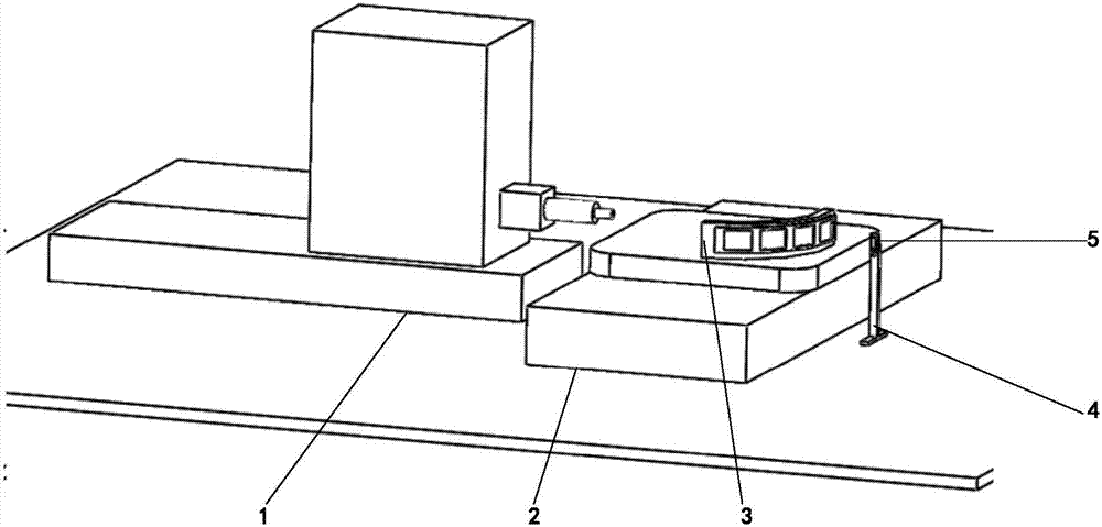
[0055] Such as figure 2 As shown, an in-situ measurement system for the wall thickness of thin-walled components, the system includes: CNC machine tool 1, turntable 2, profiling fixture 3, probe bracket 4, binocular structured light measurement equipment 5, industrial computer and high-speed communication unit, where:

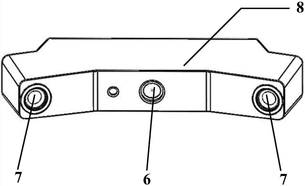
[0056] Described binocular structured light measurement equipment 5 comprises a digital projector 6, two CCD industrial cameras 7, and aluminum alloy base 8 (as image 3 shown),...


PUM


Abstract

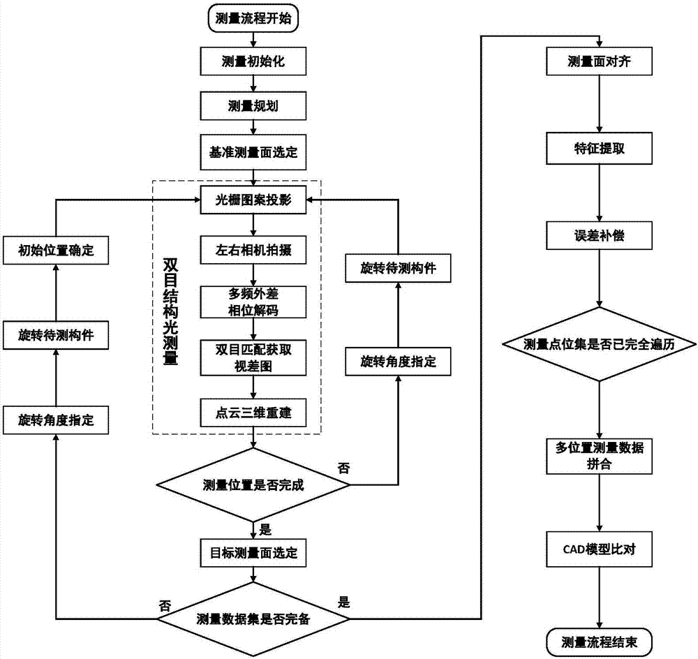
The invention discloses a system and a method for in-situ measurement of the wall thickness of a large thin-walled component. The system includes a numerical control machine tool, a tracer fixture, a measuring head bracket, a binocular structured light measurement device, an industrial computer, and a high-speed communication unit. The method is based on a binocular structured light measurement technology. Point cloud information is acquired according to the requirement on in-site detection of the overall 3D shape and wall thickness distribution of a thin-walled component in the machining process and based on a structured light precision measurement technology. The wall thickness at a corresponding position is acquired by selecting a measurement datum plane and performing differential operation gradually. Finally, the point cloud data measured at multiple positions is compared with a CAD model of the component and merged, and thus, in-situ detection of the large thin-walled component is completed, and accurate wall thickness data at each position is acquired. Precision measurement of a large thin-wall component is realized without contact. The system and the method can provide shape data for machining quality evaluation, and also can guide the machining process.

Description

technical field [0001] The invention relates to an in-situ optical measurement system and method for the wall thickness of a large thin-walled component, in particular to an in-situ measurement system and method for the wall thickness of a large-scale thin-walled component that integrates binocular grating projection measurement and a numerically controlled machine tool, and belongs to Technical fields of mechanical engineering and optical engineering. Background technique [0002] In the key industrial fields of the national economy such as automobiles, aviation, aerospace and shipbuilding, there are a large number of large thin-walled components, such as launch vehicle propellant tanks, space station cabins, large aircraft wing skins, ship propeller blades and automobile bodies. Main model checker, etc. As an important part of each system, the machining accuracy of large thin-walled components is directly related to the overall mechanical properties of the system, and its...

Claims


Application Information

Patent Timeline
Patent Type & Authority Applications(China)
IPC IPC(8): G01B11/06
CPCG01B11/06
Inventor 陈晓波刘晓习俊通吴卓琦杜辉郭根侯春杰南博华
Owner SHANGHAI JIAO TONG UNIV
Learn More