
High-speed structured light imaging system

A technology of structured light imaging and optical imaging, applied in optics, optical components, nonlinear optics, etc., can solve the problems of slow imaging speed and restricting imaging frame rate of structured light system.

Active Publication Date: 2020-04-17
TSINGHUA UNIV
View PDF1 Cites 0 Cited by
  • Summary
  • Abstract
  • Description
  • Claims
  • Application Information

AI Technical Summary

Problems solved by technology

However, the imaging speed of the existing structured light imaging method is slow, which seriously restricts the imaging frame rate of the structured light system.

Method used


Image

  • High-speed structured light imaging system
  • High-speed structured light imaging system

Examples


Embodiment Construction

[0037] Hereinafter, preferred embodiments of the present invention will be described in detail with reference to the accompanying drawings. Note that in this specification and the drawings, substantially the same steps and elements are denoted by the same reference numerals, and repeated explanation of these steps and elements will be omitted.

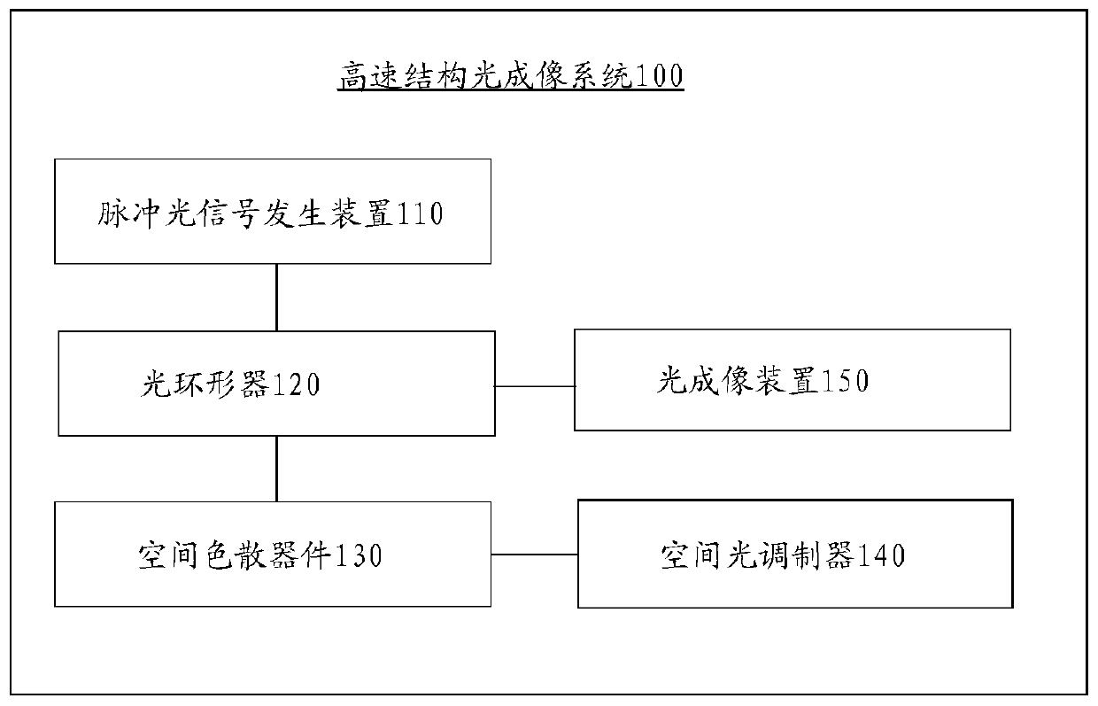
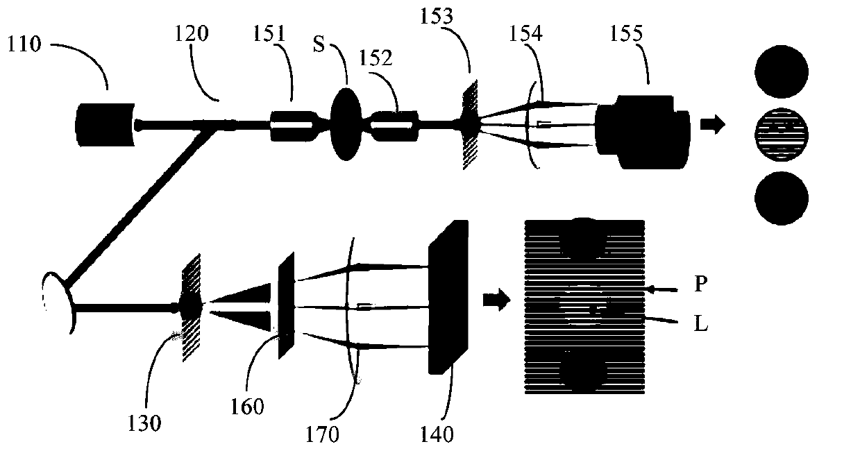
[0038] figure 1 A schematic structural view of a high-speed structured light imaging system 100 according to an embodiment of the present invention is described. The following will refer to figure 1 A high-speed structured light imaging system according to an embodiment of the present invention will be described. see figure 1 , the high-speed structured light imaging system 100 includes: a pulsed light signal generating device 110 , an optical circulator 120 , a spatial dispersion device 130 , a spatial light modulator 140 and an optical imaging device 150 . The pulsed light signal generating device 110 is used for generating a pul...


PUM


Abstract

The invention relates to a high speed structure light imaging system. The high speed structure light imaging system comprises a pulse light signal generation device, a light circulator, a space dispersion device, a space light modulator and a light imaging device, wherein the pulse light signal generation device is used for generating a pulse light signal, the light circulator is used for adjusting a light path to make the pulse light signal incident from the pulse light signal generation device enter a first light path through the light circulator and return from the first light path to be incident into the light imaging device, the space dispersion device is arranged on the first light path and is used for expanding frequency spectrum of the pulse light signal incident from the light circular in the space, the space light modulator is arranged on the first light path and is used for modulating the light signal expanded in the space, and the light imaging device is used for utilizing the light signal modulated by the space light modulator to carry out imaging of a target object. The high speed structure light imaging system is advantaged in that the time for reconstructing a high resolution image is shortened, and a high speed structure light super-resolution imaging system is realized.

Description

technical field [0001] Embodiments of the present invention relate to a high-speed structured light imaging system. Background technique [0002] For many years, the resolution of wide-field / confocal fluorescence microscopy has been limited by the Abbe / Rayleigh limit of light, and structures below 200nm cannot be resolved. Effective tool. Current super-resolution imaging techniques mainly include super-resolution microscopy imaging methods based on single-molecule imaging, such as photoactivated localization microscopy (PALM) and stochastic optical reconstruction microscopy (STORM). ), and the method of improving the imaging resolution by modifying the point spread function of the light source, including stimulated emission depletion microscopy (stimulated emission deplet ion, STED) and saturated structure illumination microscopy (saturated structure illumination microscopy, SSIM). Compared with the three super-resolution imaging technologies, although the resolution of SI...

Claims


Application Information

Patent Timeline
Patent Type & Authority Patents(China)
IPC IPC(8): G02B27/58G02F1/01G02F1/29
CPCG02B27/58G02F1/01G02F1/29
Inventor 陈宏伟郭强陈明华谢世钟
Owner TSINGHUA UNIV
Learn More