Contactless energy transmission device and method for use on satellites

A non-contact, energy transmission technology, applied in the field of electronics, can solve the problems of low transmission efficiency, low coil coupling coefficient, unfavorable transmission efficiency, etc., and achieve high energy transmission efficiency, slight magnetic flux leakage, and high transmission conversion rate.

Active Publication Date: 2020-09-08
HARBIN INST OF TECH
View PDF5 Cites 0 Cited by
  • Summary
  • Abstract
  • Description
  • Claims
  • Application Information

AI Technical Summary

Problems solved by technology

[0004] The first type: a magnetically coupled non-contact energy transmission device, but this method usually has energy leakage, which may potentially interfere with other surrounding electronic equipment, and the coil coupling coefficient is low, resulting in low energy transmission efficiency.
[0005] The second type: inductive resonance coupling type, compared with magnetic coupling type, due to the self-resonance of the primary and secondary operating frequencies, the interference to peripheral equipment is small, but there are still serious problems of energy leakage and low transmission efficiency
[0006] The third type: use a non-contact energy transmission device of the separation transformer type, specifically, a transformer with a certain gap between the primary and secondary for energy transmission, and the transmission efficiency is improved, but due to the problem of its own gap, it leads to the problem of magnetic flux leakage serious
[0007] The above three methods all have the problem of energy leakage, which is not conducive to improving the transmission efficiency. Moreover, due to the compact installation of the equipment on the satellite, the space coupling between the equipment is large, and due to the limitation of the weight space, it is difficult to implement shielding measures, and the leakage magnetic field is easy to cause damage to the satellite. Other equipment has an impact, not suitable for use in satellite systems

Method used


Image

  • Contactless energy transmission device and method for use on satellites
  • Contactless energy transmission device and method for use on satellites
  • Contactless energy transmission device and method for use on satellites

Examples


Embodiment Construction

[0061] The technical solutions of the present invention will be further described in detail below in conjunction with the accompanying drawings and specific embodiments.

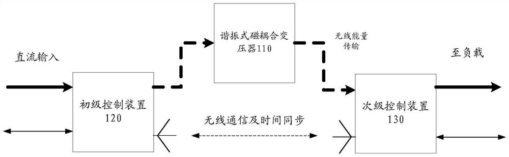
[0062] Such as figure 1 As shown, this embodiment provides a non-contact energy transmission device used on satellites, including: a resonant magnetic coupling transformer 110, a primary control device 120 and a secondary control device 130;

[0063] The resonant magnetic coupling transformer 110 includes: a primary coil and a secondary coil; wireless energy transmission is performed between the primary coil and the secondary coil through magnetic coupling;

[0064] The primary control device 120 is connected with the primary coil, and is used for converting the input DC into the pulse current required by the primary coil, and inputting the pulse current to the primary coil, and controlling the pulse current The frequency makes the resonant magnetic coupling transformer work at the resonant frequency;

[0...


PUM


Abstract

An embodiment of the invention discloses a noncontact energy transmission device used on a satellite and a method thereof. The noncontact energy transmission device used on the satellite comprises the components of a resonant magnetic coupling transformer, a primary controlling device and a secondary controlling device. The resonant magnetic coupling transformer comprises a primary coil and a secondary coil. The primary coil performs wireless energy transmission with the secondary coil through magnetic coupling. The primary controlling device is connected with the primary coil and is used for converting input DC current to pulse current which is required for the primary coil, inputting the pulse current into the primary coil, and making the resonant magnetic coupling transformer work in the resonant frequency through controlling the frequency of the pulse current. The secondary controlling device is connected with the secondary coil and is used for converting AC secondary current which is received by the secondary coil from the primary coil through magnetic coupling to output DC current.

Description

technical field [0001] The invention relates to the field of electronic technology, in particular to a non-contact energy transmission device and method used on satellites. Background technique [0002] The non-contact energy transmission device is a device for energy transmission through a wireless alternating electromagnetic field. At present, the scheme commonly used on satellites to transmit electric energy between two parts in relative motion is the slip ring scheme, and the energy is transmitted between the two parts through brushes and slip rings. This method has high transmission power, but there is direct contact between the two parts. After long-term use, there will be problems such as brush wear and metal debris, which seriously affect the reliability of the system. [0003] In the field of non-contact energy transmission, common wireless energy transmission devices in the prior art include the following three types: [0004] The first type: a magnetically coupl...

Claims


Application Information

Patent Timeline
Patent Type & Authority Patents(China)
IPC IPC(8): H02J50/10H02J7/00H01F38/14H01F27/30
CPCH01F27/306H01F38/14H01F2038/143H02J7/025
Inventor 曹喜滨王峰冯田雨董立珉韦明川陈雪芹
Owner HARBIN INST OF TECH
Why Eureka
Try Eureka