Closed water sealed well and drainage system for oil and gas field with sulfur

A closed water and oil and gas field technology, applied in waterway systems, sewer pipeline systems, drainage structures, etc., can solve the problems of poor sealing and poor safety of water-sealed wells

Pending Publication Date: 2017-10-24
PETROCHINA CO LTD
View PDF7 Cites 0 Cited by
  • Summary
  • Abstract
  • Description
  • Claims
  • Application Information

AI Technical Summary

Problems solved by technology

[0005] The invention provides a closed water-sealed well and a drainage system for sulfur-containing oil and gas fields to overcome the defects of the prior art that the water-sealed well is not tightly sealed and has poor safety

Method used


Image

  • Closed water sealed well and drainage system for oil and gas field with sulfur
  • Closed water sealed well and drainage system for oil and gas field with sulfur

Examples


Embodiment 1

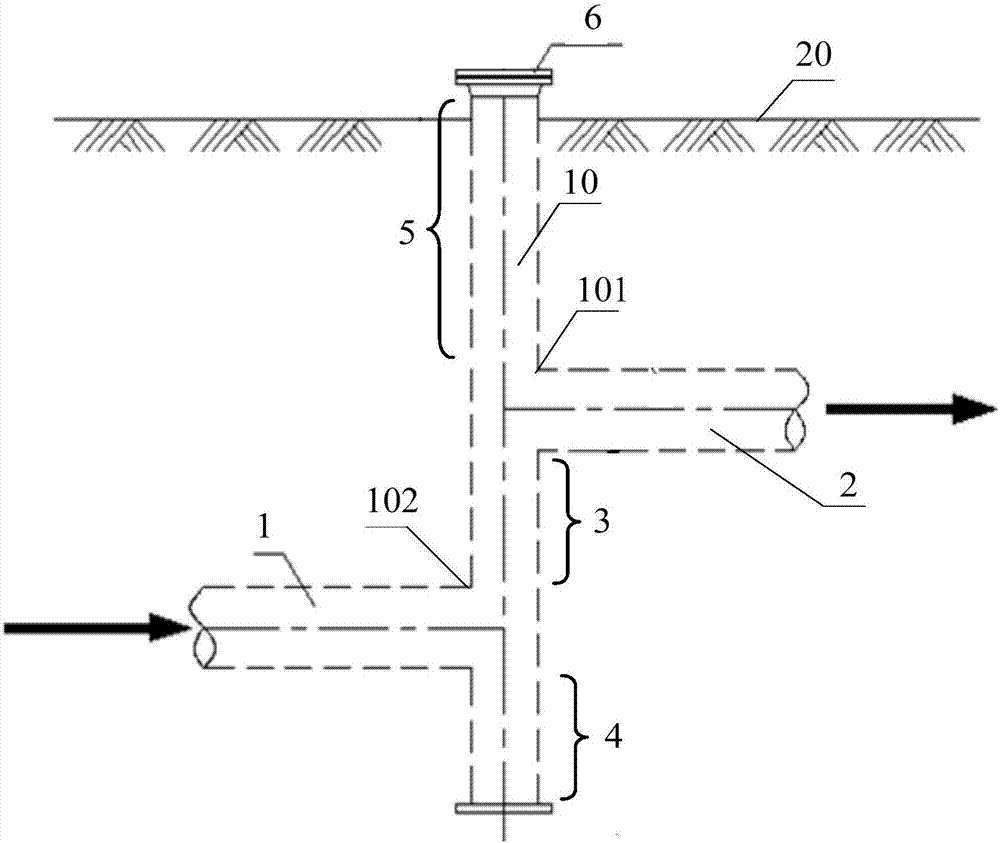
[0049] figure 1 A schematic structural diagram of a closed water-sealed well used in a sulfur-containing oil and gas field provided by an embodiment of the present invention. Refer to attached figure 1 As shown, this embodiment provides a closed water-sealed well for sulfur-containing oil and gas fields.

[0050] The closed water-sealed well for sulfur-containing oil and gas fields in this embodiment includes: a vertical pipe 10 , a first branch pipe 1 , a second branch pipe 2 , and a flange cover 6 .

[0051] A first bypass port 102 and a second bypass port 101 are provided on the tube wall of the vertical pipe 10, and the first bypass port 102 and the second bypass port 101 are located on opposite sides of the vertical pipe 10, for example, attached figure 1As shown, the first bypass port 102 is located on the left side of the vertical pipe 10 , and the second bypass port 101 is located on the right side of the vertical pipe 10 . And the second bypass port 101 is located ...

Embodiment 2

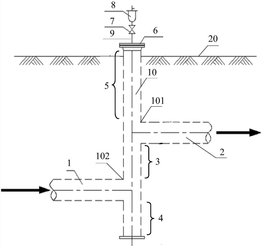
[0066] figure 2 A schematic structural diagram of a closed water-sealed well used in a sulfur-containing oil and gas field provided by another embodiment of the present invention. Refer to attached figure 2 As shown, this embodiment provides another structure for closed water-sealed wells in sour oil and gas fields.

[0067] The difference between the closed water-sealed well for sulfur-containing oil and gas fields of this embodiment and the closed-type water-sealed well for sulfur-containing oil and gas fields provided in Example 1 is that: the flange cover 6 of the water-sealed well of this embodiment is also An exhaust pipe 9 is provided, and the exhaust pipe 9 communicates with the vertical pipe 10 . The exhaust pipe 9 is also provided with a control valve for controlling the air pressure in the vertical pipe 10 .

[0068] Specifically, the control valve includes: a cut-off valve 7 and a breathing valve 8 . The shut-off valve 7 is located above the flange 6, and the ...

Embodiment 3

[0076] This embodiment provides a drainage system for sulfur-containing oil and gas fields. The drainage system includes: a drainage pipe network and a closed water-sealed well, wherein the closed water-sealed well is connected to the drainage pipe network.

[0077] The closed water-sealed well in this embodiment has the same structure as the closed water-sealed well used in the above-mentioned embodiment 1 or embodiment 2 for sulfur-containing oil and gas fields, and will not be described here one by one. For details, please refer to embodiment 1 Or the description of embodiment two.

[0078]In the drainage system provided in this embodiment, by connecting the water seal well in the drainage pipe network, since the second bypass port connected to the water outlet pipe in the water seal well is located above the first bypass port connected to the water inlet pipe, and vertically The pipe section of the pipe between the first bypass port and the second bypass port is formed as ...


PUM

PropertyMeasurementUnit
Lengthaaaaaaaaaa
Lengthaaaaaaaaaa

Abstract

The invention discloses a closed water sealed well and drainage system for an oil and gas field with sulfur. The closed water sealed well comprises a vertical pipe, a first branch pipe, a second branch pipe and a blind flange, wherein the first branch pipe is communicated with a water inlet pipe, and wherein the second branch pipe is communicated with a water outlet pipe; a first bypass orifice and a second bypass orifice which are located at the opposite two sides of the vertical pipe are formed in the pipe wall of the vertical pipe, and the second bypass orifice is located on the first bypass orifice; the first branch pipe is communicated with the vertical pipe through the first bypass orifice, the second branch pipe is communicated with the vertical pipe through the second bypass orifice, and the pipe section between the top end of the vertical pipe and the second bypass orifice is an inspection section; the pipe section between the first bypass orifice and the second bypass orifice is a water sealing section; the pipe section under the first bypass orifice is a mud precipitation section; the blind flange is connected with the top end of the vertical pipe in a sealing mode. Therefore, toxic gases in the drainage system are kept in a sealed pipeline and do not leak. When one place in the drainage system burns, the water sealing section can prevent fire from spreading, so that the safety of operators on the scene is guaranteed, and the environment pollution is reduced.

Description

technical field [0001] The invention relates to the technical field of oilfield equipment, in particular to a closed water-sealed well and a drainage system for sulfur-containing oil and gas fields. Background technique [0002] At present, the collection of sulfur-containing sewage in sour natural gas purification plants in most oil and gas fields adopts gravity flow transportation, that is, the sulfur-containing sewage flows along the pipelines in the drainage network under the action of its own gravity and is discharged. This collection method needs to use inspection wells and water seal wells to connect the drainage pipes. [0003] There are toxic gases in the drainage pipes, such as hydrogen sulfide. Hydrogen sulfide is a colorless gas and is a flammable hazardous chemical. If it overflows from the drainage pipes, it will mix with air to form an explosive mixture, which will cause combustion when exposed to open flames or high heat. Explosions, fires, poisoning and oth...

Claims


Application Information

Patent Timeline
IPC IPC(8): E03F3/02E03F5/24E03F5/02
CPCE03F3/02E03F5/021E03F5/24
Inventor 孟波杨洋艾国生赵琼吴超何蓉云宋美华石玉芬宫彦双吴梅竹高洁玉冯鹏洲张爱良黄建敏王坤喻友军金光明杨其展张卫朋梁林程美林
Owner PETROCHINA CO LTD
Why Eureka
Try Eureka