
Modulation and demodulation method and device for optical fiber grating sensor based on phase shift signal modulation

A fiber grating, modulation and demodulation technology, applied in the direction of measuring devices, instruments, using wave/particle radiation, etc., can solve the problems of high hardware system requirements, difficult modulation, slow solution speed, etc., and achieve high signal-to-noise ratio, Strong anti-interference ability and small size effect

Active Publication Date: 2017-10-24
NANJING UNIV OF SCI & TECH
View PDF7 Cites 9 Cited by
  • Summary
  • Abstract
  • Description
  • Claims
  • Application Information

AI Technical Summary

Problems solved by technology

[0004] The purpose of the present invention is to provide a fiber grating sensing modulation and demodulation method and device based on phase-shift signal modulation, which solves the problem of difficult modulation of traditional phase detection technology, susceptibility to interference, high hardware system requirements, slow solution speed, multiple Hardware complex problems in area detection

Method used


Image

  • Modulation and demodulation method and device for optical fiber grating sensor based on phase shift signal modulation
  • Modulation and demodulation method and device for optical fiber grating sensor based on phase shift signal modulation
  • Modulation and demodulation method and device for optical fiber grating sensor based on phase shift signal modulation

Examples


Embodiment 1

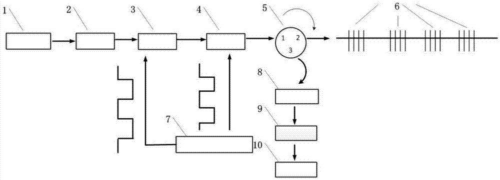
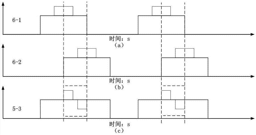
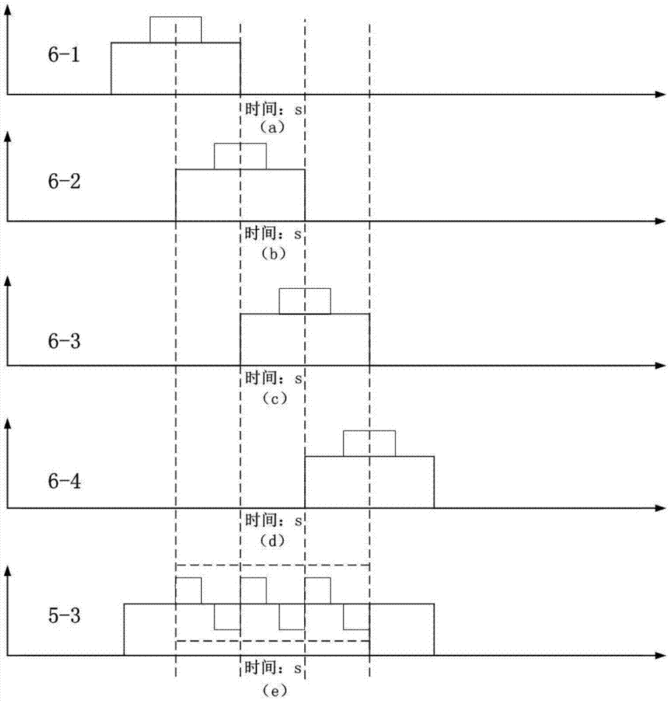
[0052] The vibration information of a fiber grating sensor is tested in experiments. The distance between the two grating fibers is 24m, the sampling time is 22s, the laser pulse cycle and the frequency of the phase modulation pulse are 1MHz, and the pulse width of the phase modulation in one cycle is 160ns. The measuring device is as follows: figure 1 As shown, the measurement steps are:

[0053] Step 1. Turn on the laser light source 1 and let the tester walk around the optical fiber to which the fiber grating group 6 is fused, so that the fiber grating group 6 is induced to vibrate, and the light emitted by the laser light source 1 passes through the isolator 2, the optical switch 3 and the phase modulator in sequence 4. The signal generator 7 generates a high-speed pulse signal with a frequency of 1 MHz, which acts on the optical switch 3 to generate continuous laser pulses, and simultaneously provides a phase modulation of π / 2 to the phase modulator 4 to form a phase-modul...


PUM


Abstract

The invention discloses a modulation and demodulation method and device for an optical fiber grating sensor based on phase shift signal modulation. The modulation and demodulation device comprises a laser source, an isolator, an optical switch, a phase modulator, a circulator, an optical fiber grating group, a signal generator, a photoelectric converter, a data acquisition module and a data processing module, and is characterized in that the laser source is modulated by using the optical switch so as to generate a pulse beam, then high-speed pulse phase modulation is performed on the pulse beam by using the phase modulator, the pulse beam is interfered in the circulator, multipath phase shift signals are generated and outputted via a third port, and vibration phase demodulation for an optical fiber sensor is realized by being cooperated with a demodulation method of a multipath phase shift algorithm. The modulation and demodulation method is simple in optical path, capable of forming a plurality of sensing modules conveniently, low in modulation requirement, simple in demodulation circuit, high in real-time performance and precision, wide in dynamic range and high in environmental interference resisting ability.

Description

technical field [0001] The invention belongs to the technical field of optical fiber sensing, and in particular relates to a fiber grating sensing modulation and demodulation method and device based on phase-shift signal modulation. Background technique [0002] With the rapid development of science and technology, human society has entered the information age of rapid development. Internet of things technology, communication technology and computer have become information technology with rapid development. On this basis, the sensor network in the Internet of Things has received more and more close attention. In the development of information technology, various industries are inseparable from sensors, such as industrial control, automated production process, environmental monitoring, oil pipeline monitoring, biomedicine, security monitoring, bridge and tunnel monitoring, etc. There are traces of sensors. Compared with traditional electronic sensors, fiber optic sensors ha...

Claims


Application Information

Patent Timeline
Patent Type & Authority Applications(China)
IPC IPC(8): G01H9/00
CPCG01H9/004
Inventor 王青王晓烨任仲杰朱日宏王海林李建欣
Owner NANJING UNIV OF SCI & TECH
Learn More