

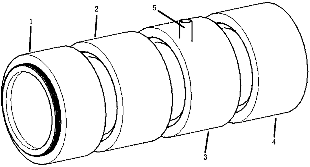
A vacuum temperature-controlled optical path purification device
A purification device and vacuum purification technology, applied in the optical field, can solve problems such as damage to the molecular pool, condensation molecules on the end surface, inaccurate measurement results, etc., to prolong the service life and prevent the effect of air heat conduction
- Summary
- Abstract
- Description
- Claims
- Application Information
AI Technical Summary
Problems solved by technology
Method used
Image

Examples
Embodiment 1
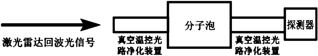
[0038] Such as figure 2 As shown, in the daytime observation lidar system, due to the strong background light noise, the background light noise needs to be suppressed, so the molecular pool needs to be used. Therefore, the vacuum temperature is placed on the left and right sides of the molecular pool. A control purification device, and a detector is installed on the right side of the vacuum temperature control purification device on the right side of the molecular pool. The backscattered echo signal of the laser radar first passes through the vacuum temperature-controlled purification device on the left, and then enters the left end face of the molecular pool, and the light passing through the molecular pool passes through the right end face of the molecular pool, and enters the right end face of the molecular pool. The vacuum temperature-controlled purification device enters the detector for collection and analysis. In this way, by installing a vacuum temperature-controlled ...
Embodiment 2
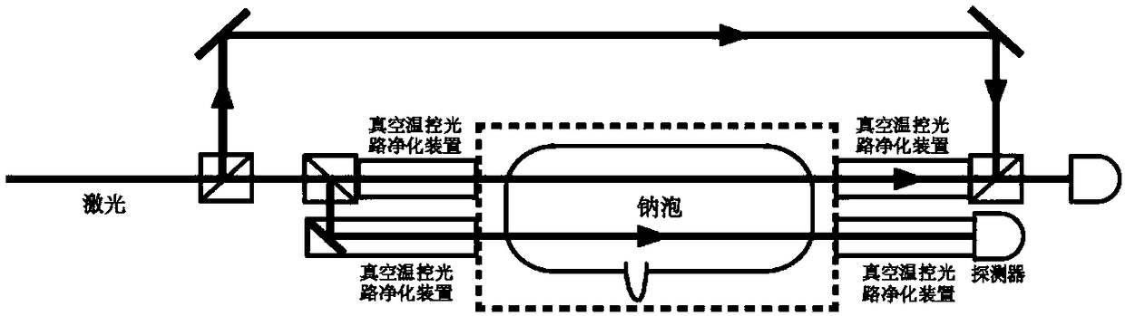
[0040] Such as image 3 As shown, in the sodium layer wind and temperature measurement lidar system, the 589nm continuous laser light passes through two beam splitters and two vacuum temperature-controlled optical path purification devices respectively, and then enters the sodium atom pool. After passing through two vacuum temperature-controlled optical path purification devices, they enter the detector respectively, and are collected and analyzed by the data analysis system. By installing a vacuum temperature-controlled purification device, the optical paths on the left and right sides of the sodium atom pool can be purified, and the heat conduction effect of molecules can be avoided to reduce the damage to the molecular pool due to ambient temperature changes. In the sodium layer wind and temperature measurement lidar system, the measurement parameters are calculated according to the molecular Doppler frequency shift. Therefore, the laser emission frequency needs to be prec...
PUM
 Abstract
Description
Claims
Application Information