Eureka AIR delivers breakthrough ideas for toughest innovation challenges, trusted by R&D personnel around the world.

The Dressing Method of Composite Sectional Profile of Optical Machining Parallel Diamond Grinding Wheel

A diamond grinding wheel and optical processing technology, which is applied in metal processing equipment, manufacturing tools, grinding/polishing equipment, etc., can solve the problems of grinding wheel grinding performance degradation, diamond particle breakage and falling off, small-scale corrugation error, etc., and achieve grinding wheel dressing High precision, reduced depth and instability, avoiding the effect of processing stress concentration

Inactive Publication Date: 2019-12-03
LASER FUSION RES CENT CHINA ACAD OF ENG PHYSICS
View PDF9 Cites 0 Cited by
  • Summary
  • Abstract
  • Description
  • Claims
  • Application Information

AI Technical Summary

Problems solved by technology

In addition, when using a single-point diamond pen to modify the diamond grinding wheel, the interaction between the two superabrasives will easily lead to serious wear of the diamond pen, and at the same time, the diamond particles on the surface of the diamond grinding wheel will be damaged and fall off, resulting in a decline in the grinding performance of the grinding wheel, which is not suitable for optics. Processing field
[0004] CN201510263137A discloses an arc grinding wheel online dressing device based on the spherical envelope of a cup-shaped tool, which can realize online dressing of aspheric grinding arc diamond grinding wheels. Severe small-scale ripple errors are also introduced when planar components

Method used


Image

  • The Dressing Method of Composite Sectional Profile of Optical Machining Parallel Diamond Grinding Wheel
  • The Dressing Method of Composite Sectional Profile of Optical Machining Parallel Diamond Grinding Wheel
  • The Dressing Method of Composite Sectional Profile of Optical Machining Parallel Diamond Grinding Wheel

Examples


Embodiment

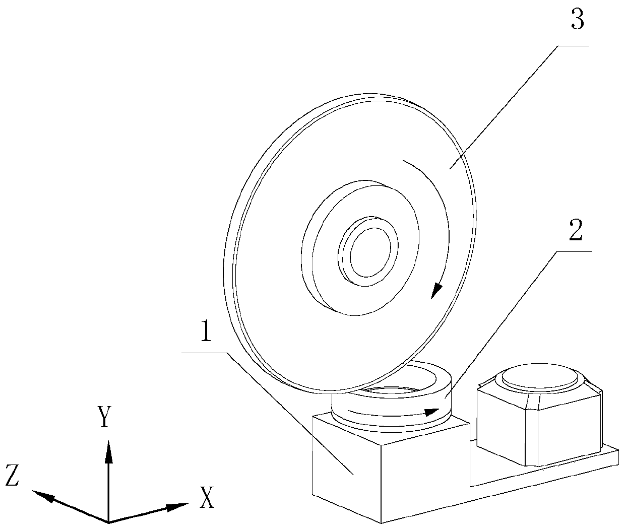
[0038] The trimming object of this embodiment is a Φ400mm×20mm parallel diamond grinding wheel, the particle size is 1800#, and the bonding agent is resin. The size of the dressing wheel is Φ100mm×40mm, the particle size is 1500#, and the abrasive grain is green silicon carbide (GC). The steps of the trimming method for the optical processing parallel diamond grinding wheel composite cross-sectional profile in this embodiment are as follows:

[0039] 1) Install the diamond grinding wheel 3 on the main shaft of the ultra-precision surface grinder, fix the dresser 2 on the workbench of the ultra-precision surface grinder, and use the mandrel and the dial gauge to adjust the axis of rotation of the dressing wheel 2 on the dresser 1 and the machine tool Parallelism between the Y axes. In order to reduce small-scale ripples on the surface of the processing element, the axial parallelism of the diamond grinding wheel 3 must not be greater than 3 μm. Therefore, according to formula...


PUM


Abstract

The invention provides a finishing method for a composite section contour of a center straight line and two lateral edges arc transitions of a parallel diamond grinding wheel for optical machining; the method comprises the steps of 1) adjusting parallelism between a rotary shaft of a finishing grinding wheel on a finishing device and a vertical Y axis of an ultra-precision surface grinder; 2) using the finishing grinding wheel, by means of end grinding, to polish an outer peripheral face of the diamond grinding wheel so that the outer peripheral face of the diamond grinding wheel gains peripheral runout precision and axial parallelism meeting the requirements of machining techniques; 3) adjusting a feeding direction of the diamond grinding wheel to be inclined angularly to an X axis of the ultra-precision surface grinder, and using the finishing grinding wheel, by means of end grinding, to grind the two lateral edges of the diamond grinding wheel into smooth arcs. Diamond grinding wheel dressing and truing are performed at the same time, so that it is possible to accurately acquire width of the center line segment and height of the arc transitions on two sides, machining stress concentration caused to edges of the grinding wheel during grinding is effectively avoided, and sub-surface defect depth and instability of a component are decreased.

Description

technical field [0001] The invention relates to the field of ultra-precision grinding of optical elements, in particular to the compound cross-sectional profile of the central flat line and the arc transition of both sides of the parallel diamond grinding wheel used in the process of grinding subsurface defects and depth stability control of optical elements trimming method. Background technique [0002] Transmissive optical elements are widely used in high-power laser devices, and their processed subsurface defects have an important impact on the anti-laser damage threshold of the element and the overall output performance of the entire device. Ultra-precision forming grinding of optical components by using fixed abrasive parallel diamond grinding wheels can efficiently obtain high-precision optical surfaces, but at the same time, it is necessary to strictly control the quality of subsurface defects in full aperture to facilitate subsequent polishing processing on grinding ...

Claims


Application Information

Patent Timeline
Patent Type & Authority Patents(China)
IPC IPC(8): B24D18/00B24B53/12
CPCB24B53/12B24D18/00
Inventor 周炼赵世杰袁志刚谢瑞清陈贤华刘民才张清华王健
Owner LASER FUSION RES CENT CHINA ACAD OF ENG PHYSICS
Why Eureka
Eureka Blog
Learn More