Direct-current trimming module and band-gap reference circuit adopting direct-current trimming

A technology for trimming and decoding modules, which is applied in the direction of adjusting electrical variables, control/regulation systems, instruments, etc., and can solve the problems of the influence of temperature characteristics of the bandgap reference circuit 100 and the deterioration of voltage accuracy, so as to ensure performance and reduce Effect of offset voltage and difficulty reduction

Active Publication Date: 2021-07-16
SG MICRO
View PDF7 Cites 4 Cited by
  • Summary
  • Abstract
  • Description
  • Claims
  • Application Information

AI Technical Summary

Problems solved by technology

[0005] However, in the actual interband reference circuit 100, the output voltage VOUT is also affected by the offset voltage of the amplifier 110
The performance of the amplifier 110 is affected by the mismatch of the integrated circuit process and the finite gain of the amplifier. There is a non-negligible offset voltage VOS between the non-inverting input terminal and the inverting input terminal, which causes the voltage accuracy of the output voltage VOUT generated at the output terminal to change. Difference
Since the offset voltage VOS of the amplifier 110 is related to temperature, the temperature characteristics of the bandgap reference circuit 100 will also be affected

Method used


Image

  • Direct-current trimming module and band-gap reference circuit adopting direct-current trimming
  • Direct-current trimming module and band-gap reference circuit adopting direct-current trimming
  • Direct-current trimming module and band-gap reference circuit adopting direct-current trimming

Examples


Embodiment Construction

[0032] In order to facilitate understanding of the present invention, the present invention will be described more fully described with reference to the related drawings. The preferred embodiment of the present invention is given in the drawings. However, the present invention can be implemented in different forms and is not limited to the embodiments described herein. Conversely, the purpose of providing these embodiments is to make the understanding of the disclosure of the present invention more thoroughly.

[0033]All techniques and scientific terms used herein are identical to those skilled in the art, unless otherwise defined. The terms used herein are intended to describe the embodiments of the specific embodiments are not intended to limit the invention.

[0034] Next, the present invention will be described in detail with reference to the drawings.

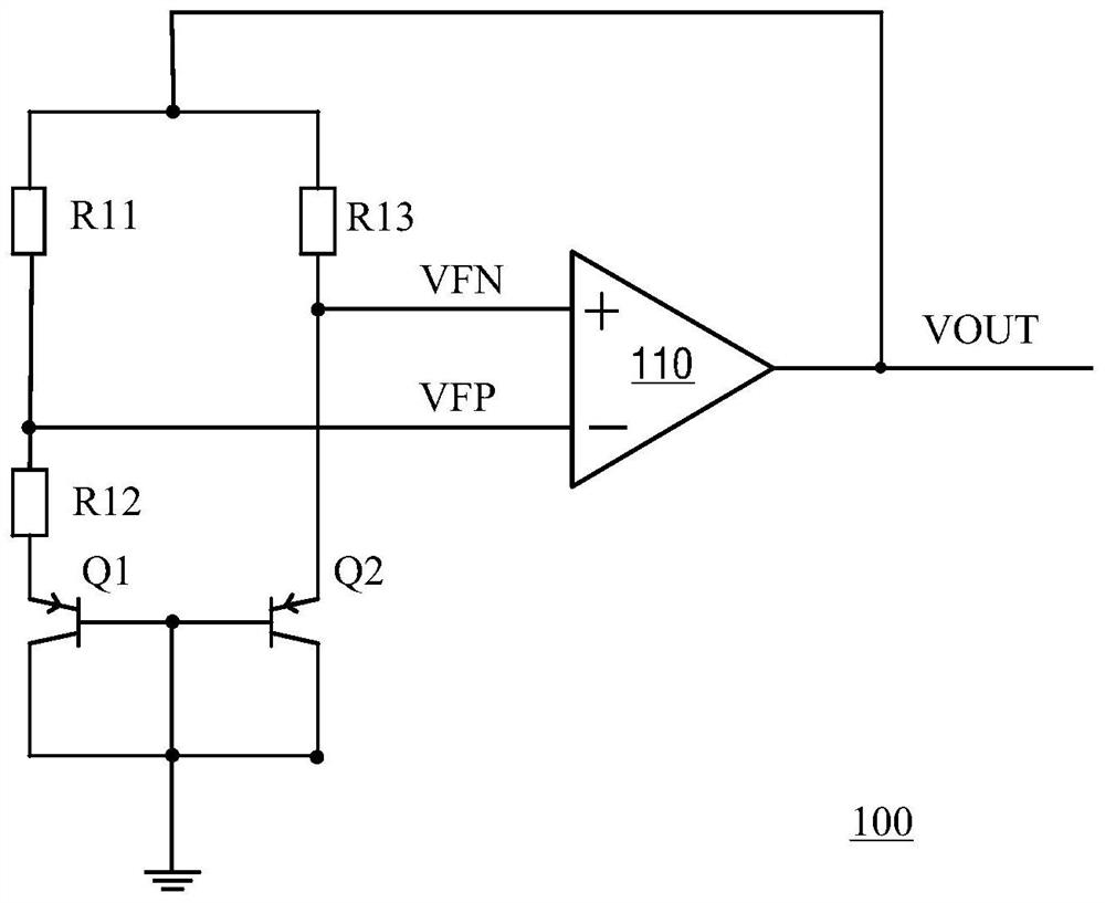
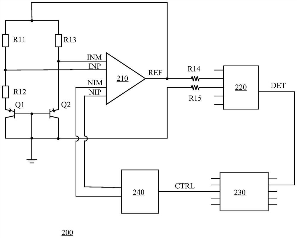
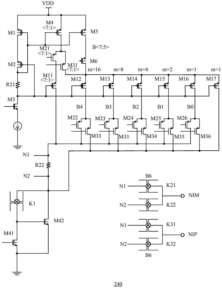
[0035] figure 2 A schematic circuit diagram of a bandgap reference circuit in accordance with an embodiment of the present...


PUM


Abstract

The invention discloses a direct current trimming module and a band-gap reference circuit adopting direct current trimming. The direct current trimming module comprises a first decoding module which generates a first current with a corresponding magnitude according to the weight and the numerical value of a first group of data bits of a control word, a second decoding module which is used for generating a second current with a corresponding magnitude according to the weight and the numerical value of a second group of data bits of the control word, a current sampling module which is used for superposing the first current and the second current to obtain a trimming current and converting the trimming current into a trimming voltage, and a polarity selection module which is used for providing the trimming voltage at the first output end as a first trimming signal or providing the trimming voltage at the second output end as a second trimming signal according to the numerical values of the third group of data bits of the control word. The direct current trimming module is adopted to perform feedback trimming on the output signal of the amplifier so as to reduce the offset voltage of the amplifier so that the precision and the temperature stability of the reference voltage generated by the band-gap reference circuit are improved.

Description

Technical field [0001] The present invention relates to the field of electronic circuit technology, and more particularly to a DC trimming module and a bandgap reference circuit using DC. Background technique [0002] The band gap reference circuit is a reference voltage circuit that is often used in an integrated circuit for providing a high precision reference voltage that is not affected by the supply voltage and ambient temperature. [0003] Such as figure 1 As shown, the bandgap reference circuit 100 according to the prior art includes, for example, bipolar transistors Q1 and Q2, resistors R11 to R13, and amplifier 110. The resistor R11, the resistor R12, and the bipolar transistor Q1 are sequentially connected between the power supply terminal and the ground, wherein the intermediate node of the resistor R11 and the resistor R12 is a first node. The resistor R13 and the bipolar transistor Q2 are sequentially connected between the power supply terminal and the ground, and th...

Claims


Application Information

Patent Timeline
Patent Type & Authority Applications(China)
IPC IPC(8): G05F1/567
CPCG05F1/567
Inventor 满雪成
Owner SG MICRO
Why Eureka
Try Eureka