Piston valve and using and sealing method thereof

A technology for piston valves and pistons, which is applied to multi-way valves, valve devices, engine components, etc., can solve the problems of unguaranteed sealing, complex valve structure, large pressure loss, etc., and achieve long anti-cavitation time and good sealing effect , The effect of small opening force of the structure

Inactive Publication Date: 2017-10-27
DALIAN CONSERVATION SCI & TECH CO LTD
View PDF16 Cites 3 Cited by
  • Summary
  • Abstract
  • Description
  • Claims
  • Application Information

AI Technical Summary

Problems solved by technology

[0028] In view of the above-mentioned problems in the prior art: the present invention aims to provide a piston valve to solve the problems of complex structure, large pressure loss, poor sealing effect or inability to guarantee the sealing of some existing types of valves, especially to solve the problems of high temperature occasions. Sealing problems, at the same time solve the problem of deposition, coking, structure affecting the switch when the medium contains impurities, or affect the sealing after erosion and wear, and solve the problem of short service life of some valves after being cavitated

Method used


Image

  • Piston valve and using and sealing method thereof
  • Piston valve and using and sealing method thereof
  • Piston valve and using and sealing method thereof

Examples


Embodiment 1

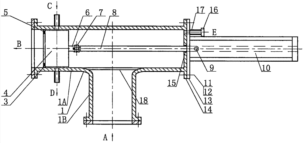
[0087] A piston valve such as figure 1 As shown, it includes a three-way valve body 1, a piston 4, a pull rod 8, a flange cover 14 and a drive mechanism 10; The pull ear 6 is hinged, and the other end is hinged with the drive mechanism 10 through the pin shaft 9; one side of the flange cover 14 is welded to one end of the straight-through pipe 1A of the valve body, and the other side is connected to the base of the drive mechanism 10 through bolts 11 Connect with the nut 12; the flange cover 14 has a hole with the same size as the pull rod 8, and the two are slidingly fitted, and the pull rod 8 always extends out of the flange cover 13. There is an annular groove on the inner surface of the hole on the flange cover, and a seal 15 is housed in the annular groove, such as a sealing ring or a sealing packing, etc.; the valve of this structure is used in occasions where sealing requirements are not strict. The medium enters through the inlet A of the valve body and flows out thro...

Embodiment 2

[0089] On the basis of Example 1, in order to further improve the sealing effect, as figure 1 As shown, the inner surface of the straight-through pipe 1A of the three-way valve body 1 is fixed with an annular valve seat 3 coaxial with the straight-through pipe 1A; the annular valve seat 3 forms a sealing surface with the axial section of the piston.

Embodiment 3

[0091] On the basis of Example 2, in order to further improve the sealing effect, an annular groove is processed on the surface of the annular valve seat 3 facing the piston 4, and a ring of elastic sealing packing or a metal hollow O-shaped groove is fixed in the groove. Ring 5, sealing packing or metal hollow O-ring 5 protrude from the surface of annular valve seat 3, such as figure 1 shown. Wherein, the elastic sealing packing is silica gel or fluororubber;

[0092] In order to prevent the deposition of impurities on the sealing surface from affecting the sealing, the outlet and inlet of the three-way valve body can be reversed and used


PUM


Abstract

The invention discloses a piston valve and a using and sealing method thereof. The piston valve comprises a three-way valve body, a piston and a driving mechanism, wherein the piston is positioned in a straight through pipe of the three-way valve body; the end of the straight through pipe is fixedly connected with a flange cover, and the other side of the flange cover is fixedly connected with the driving mechanism; a pull rod penetrates through a through hole in the flange cover and is in sliding fit with the flange cover; the two ends of the pull rod are connected with the piston and the driving mechanism respectively. An annular groove is formed in the inner surface of the through hole in the flange cover, and a sealing part is arranged in the annular groove; an air inlet and outlet structure is arranged on the flange cover. According to the piston valve and the using and sealing method thereof, the problems of complex structures of some types of valves, large pressure loss, poor sealing effect or inability to guarantee the sealing are solved, particularly the problem of sealing difficulty in the case of large caliber and high temperature is solved, and the problem that sealing is affected by deposition or erosive wear when impurities exist in the medium is solved.

Description

technical field [0001] The invention relates to sealing and valves, in particular to a piston valve and a sealing method thereof. Background technique [0002] The valves used in many occasions, such as the inlet and outlet of smoke machines used in oil refineries, some desulfurization systems and sulfur recovery systems, are in accordance with the national environmental protection requirements: the leakage is zero or the VI level of the American standard is sealed. For larger valves, it is very difficult to meet this standard. In high temperature occasions, it is more difficult to realize. For example: the inlet valve of the high-temperature smoke machine is used in the flue gas occasion with a design temperature of more than 700 degrees, with a diameter of 1800, a flue gas inlet pressure of 0.25 MPa, and a process requirement of zero leakage. The butterfly valve manufactured by the German Adams company sells for 500,000 to 600,000 US dollars per set when the size is not ...

Claims


Application Information

Patent Timeline
IPC IPC(8): F16K11/07
CPCF16K11/0708F16K11/0712
Inventor 王嘉贤张春来徐勇
Owner DALIAN CONSERVATION SCI & TECH CO LTD
Why Eureka
Try Eureka