USB2.0/3.0 HUB based on optical fiber transmission

A USB2.0, optical fiber transmission technology, applied in the direction of program control, instrument, computer control, etc., can solve the problems of interference, data security cannot be guaranteed, limited compatible applications, etc., to achieve the effect of flexible replacement

Pending Publication Date: 2017-10-27
广东启鼎光电科技有限公司
View PDF0 Cites 2 Cited by
  • Summary
  • Abstract
  • Description
  • Claims
  • Application Information

AI Technical Summary

Problems solved by technology

Since the transmission rate has been increased from 480Mbps specified in the previous USB2.0 standard to 5Gbps, the use of traditional cables generally does not exceed 3 meters. After some manufacturers use relay amplifier chips, the transmission distance can only reach a maximum of 15 meters. Transmission distance, but because cable transmission is particularly susceptible to electromagnetic interference during use, it is not suitable for use on some industrial production lines with large electromagnetic interference, and some equipment sensitive to electromagnetic interference (such as military equipment) Currently, with the rise of Industry 4.0, the transmission distance of many USB3.0 industrial cameras will exceed this distance, and even reach a distance of several hundred meters. Management, users can only use USB3.0 storage devices and USB3.0 printers at the remote end, so as to realize the safe isolation between the computer host and the user, and the distance between the computer and the terminal often reaches hundreds of meters, and the data is in the process of transmission There must be no electromagnetic leakage in the system, which will cause the data security not to be guaranteed
However, we use optical fiber to transmit USB3.0 signals to solve the problem of electromagnetic interference and the problem of transmission distance. In addition, although there are some devices that can realize long-distance transmission of USB3.0 signals, they generally use terminal equipment The USB3.0 data is parsed into other data formats by the USB3.0 physical layer chip and then re-encoded and converted into optical fiber for transmission. The other end converts the received optical signal into an electrical signal, which is converted into a parallel signal by the USB3.0 physical layer chip The data is sent to the acquisition card for data acquisition. They are all aimed at some specific equipment applications and cannot realize the access of other USB3.0 standard terminal equipment. For example, a device used to realize USB3.0 industrial camera long-distance transmission cannot It is used to access other USB3.0 terminal devices such as U disk, USB3.0 mobile hard disk or printer, and there is no one that can directly connect USB2.0 and USB3.0 devices at the same time through a single USB3.0 master The chip uses an ultra-high-speed signal differential data line to convert it into an optical signal with an optical module and then use an optical fiber to complete the long-distance transmission. Generally, a USB2.0 to USB3.0 conversion chip is added, and then a USB3.0 HUB is used for integration. Transmission, compatibility needs to be improved, and this chip is currently monopolized, and other manufacturers cannot purchase it through channels, which directly limits the compatible application of USB3.0 to USB2.0 / 1.1 / 1.0 in long-distance transmission

Method used


Image

  • USB2.0/3.0 HUB based on optical fiber transmission
  • USB2.0/3.0 HUB based on optical fiber transmission
  • USB2.0/3.0 HUB based on optical fiber transmission

Examples


Embodiment Construction

[0057] In order to better understand the present invention, the present invention will be further described below in conjunction with the accompanying drawings and embodiments. It should be understood that the specific embodiments described here are only used to explain the present invention, but not to limit the present invention. In addition, it should be noted that, for the convenience of description, only some parts related to the present invention are shown in the drawings but not all circuit structures.

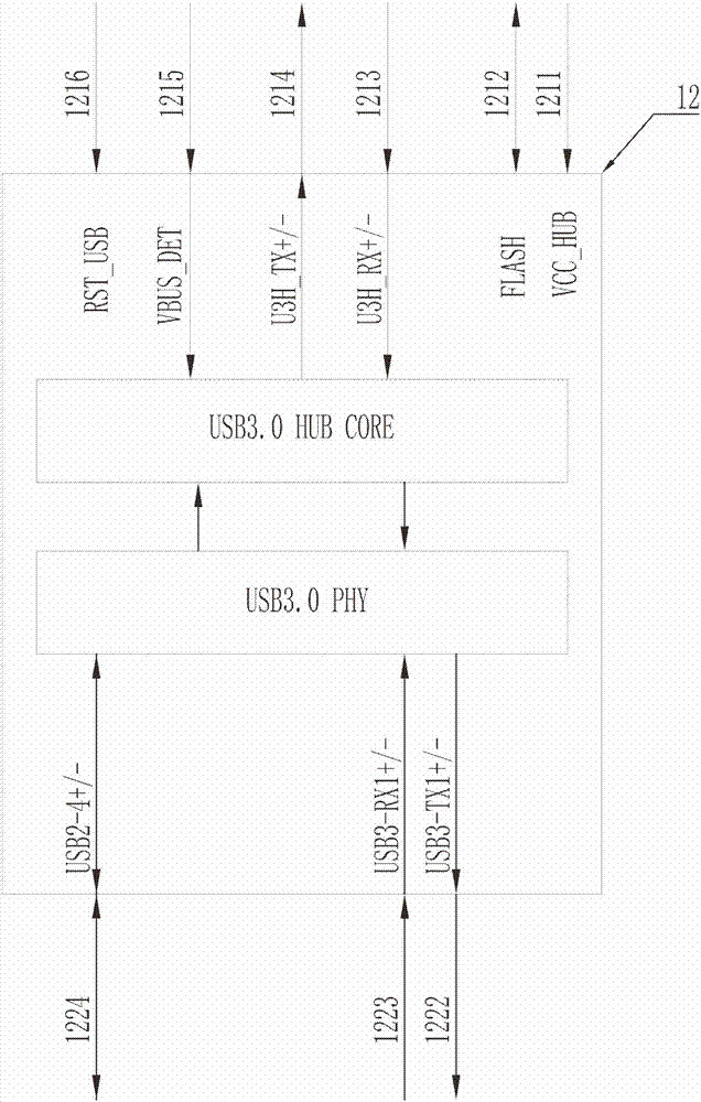
[0058] The present invention is a USB3.0 HUB that supports long-distance transmission between multiple USB3.0 terminal devices and computers based on optical fiber transmission; figure 1 As shown, one end of the USB3.0 optical fiber sending end 1 is connected to the USB3.0 HOST 3 of the host computer through a USB3.0 cable, and the other end is connected to the USB3.0 optical fiber receiving end 2 through an optical fiber; one end of the USB3.0 optical fiber receiving ...


PUM


Abstract

A USB2.0\3.0 HUB based on optical fiber transmission, characterized in that: it includes a USB3.0 optical fiber sending end and a USB3.0 optical fiber receiving end, and the USB3.0 HUB at the USB3.0 optical fiber receiving end can connect four USB3.0\2.0\1.1\1.0 terminal equipment; the USB3.0 signal is transparent during the transmission process, and all terminal peripherals that meet the USB3.0\2.0\1.1\1.0 standard can be connected normally. The present invention also provides an optical fiber communication automatic negotiation method for communication between the USB3.0 optical fiber sending end and the USB3.0 optical fiber receiving end; A method for digital diagnosis and remote control of USB3.0 terminal equipment.

Description

technical field [0001] The present invention relates to the field of USB3.0 communication, in particular to the technical field of long-distance communication between various USB3.0\2.0\1.1\1.0 terminal devices and computers, specifically a USB2.0\3.0 HUB based on optical fiber transmission . [0002] The invention also relates to an automatic negotiation method for optical fiber communication between a USB3.0 optical fiber sending end and a USB3.0 optical fiber receiving end. [0003] The invention also relates to a method for digitally diagnosing the USB3.0 optical fiber sending end and the USB3.0 optical fiber receiving end and remotely controlling the USB3.0 terminal equipment. Background technique [0004] USB3.0 has greatly improved the transmission speed. It is based on the full-duplex data transmission protocol. The era of USB2.0 has improved nearly 10 times, and now the latest USB3.1 Gen2 standard has increased the transmission rate to 10Gbps, so the data transmis...

Claims


Application Information

Patent Timeline
Patent Type & Authority Applications(China)
IPC IPC(8): G05B19/042
CPCG05B19/0423G05B2219/25257
Inventor 胡承恩
Owner 广东启鼎光电科技有限公司
Why Eureka
Try Eureka