
Synchronous control method based on continuous-casting tundish lifting hydraulic cylinder synchronous control system

A continuous casting tundish, lifting hydraulic cylinder technology, applied in manufacturing tools, casting equipment, casting melt containers, etc., can solve the problems of hydraulic system leakage, different manufacturing precision of hydraulic components, uneven load, etc.

Inactive Publication Date: 2017-11-03
MAANSHAN IRON & STEEL CO LTD
View PDF6 Cites 20 Cited by
  • Summary
  • Abstract
  • Description
  • Claims
  • Application Information

AI Technical Summary

Problems solved by technology

[0003] The embodiment of the present invention provides a synchronous control method based on the synchronous control system of the continuous casting tundish lifting hydraulic cylinder, aiming to solve the existing synchronous control method of hydraulic cylinders based on hydraulic four synchronous motors or based on independent PI regulators and proportional adjustments The synchronous control accuracy of the general master-slave hydraulic cylinder synchronous control mode of the valve is easily affected by factors such as hydraulic system leakage (such as internal leakage of the hydraulic cylinder), different manufacturing accuracy of hydraulic components, and uneven load.

Method used


Image

  • Synchronous control method based on continuous-casting tundish lifting hydraulic cylinder synchronous control system
  • Synchronous control method based on continuous-casting tundish lifting hydraulic cylinder synchronous control system
  • Synchronous control method based on continuous-casting tundish lifting hydraulic cylinder synchronous control system

Examples


Embodiment Construction

[0029] In order to make the object, technical solution and advantages of the present invention clearer, the present invention will be further described in detail below in conjunction with the accompanying drawings and embodiments. It should be understood that the specific embodiments described here are only used to explain the present invention, not to limit the present invention.

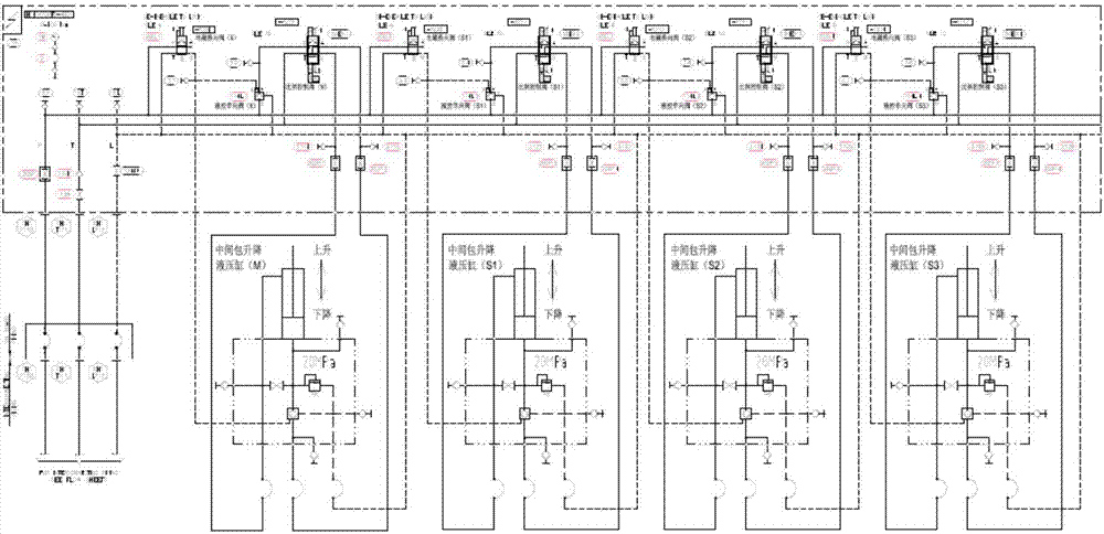
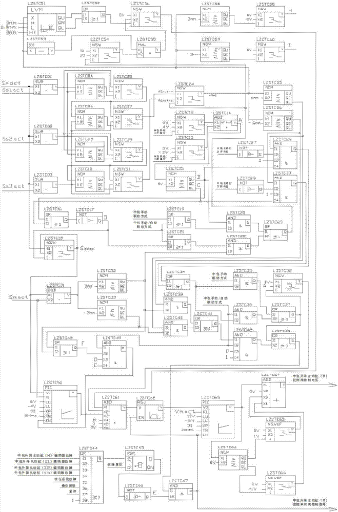
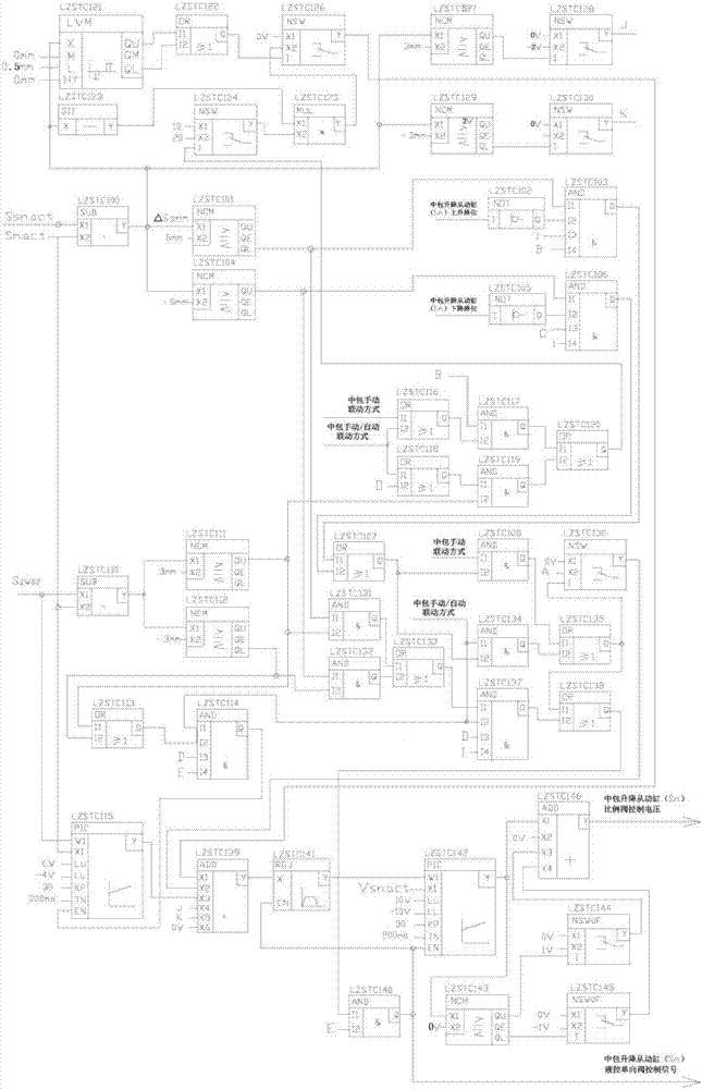
[0030] figure 1 The hydraulic system diagram of the continuous casting tundish lifting mechanism provided by the embodiment of the present invention; figure 2 Schematic diagram of the structure of the continuous casting tundish lifting active hydraulic cylinder synchronous control subsystem provided by the embodiment of the present invention, image 3 The structural schematic diagram of the continuous casting tundish lifting slave hydraulic cylinder synchronous control subsystem provided for the embodiment of the present invention, for the convenience of description, only shows the parts related ...


PUM


Abstract

The invention belongs to the field of hydraulic transmission control, and provides a synchronous control method based on a continuous-casting tundish lifting hydraulic cylinder synchronous control system. According to the method, the position deviation, beyond a set range, between a driving hydraulic cylinder and a driven hydraulic cylinder is corrected through a driving and driven hydraulic cylinder synchronous position deviation speed correction unit; if the position deviation between the driving hydraulic cylinder and the driven hydraulic cylinder is beyond the set maximum allowable position deviation, the driving hydraulic cylinder at the higher speed or the driven hydraulic cylinder at the higher speed is controlled to stop moving through a driving and driven hydraulic cylinder synchronous position deviation overrun control unit and a driven hydraulic cylinder synchronous position deviation overrun control unit till the position deviation between the driving hydraulic cylinder and the driven hydraulic cylinder is smaller than the set maximum allowable position deviation again; and a driving and driven hydraulic cylinder automatic position holding and control unit is used for preventing position deviation of the driving hydraulic cylinder and the driven hydraulic cylinder in absence of manual instructions. In this way, by adoption of the synchronous control method, under the conditions that leakage of the hydraulic cylinders occurs, the manufacturing accuracy degrees of hydraulic elements are different and loads are nonuniform, synchronous movement of the driving hydraulic cylinder and the driven hydraulic cylinder can be achieved.

Description

technical field [0001] The invention belongs to the field of hydraulic transmission control, in particular to a synchronous control method based on a synchronous control system of a continuous casting tundish lifting hydraulic cylinder. Background technique [0002] The tundish of the continuous casting machine is usually lifted and moved synchronously by four hydraulic cylinders (one active hydraulic cylinder and three slave hydraulic cylinders). For the synchronous control of the lifting hydraulic cylinders of the continuous casting tundish, currently the main use is based on hydraulic four synchronous motors The hydraulic cylinder synchronous control mode or the general master-slave hydraulic cylinder synchronous control mode based on independent PI regulators and proportional control valves. The synchronous control accuracy of these two multi-hydraulic cylinder synchronous control schemes is vulnerable to hydraulic system leakage (such as hydraulic cylinders) leakage), d...

Claims


Application Information

Patent Timeline
IPC IPC(8): F15B11/22B22D11/18
CPCF15B11/22B22D11/18F15B2211/71F15B2211/78F15B2211/86F15B2211/6656B22D41/00
Inventor 叶光平王光亚钱晓斌吴坚张乐金詹峰汪志远顾仲俊徐洪汤寅波方长德吴胜薛峰強志刚
Owner MAANSHAN IRON & STEEL CO LTD
Learn More