Correcting equipment and correcting method for luminous uniformity

A technology for uniform luminescence and equipment correction, applied in optomechanical equipment, microlithography exposure equipment, optics, etc., can solve the problems of time-consuming cost, inconvenient use, scrapped photosensitive circuit boards, etc., to ensure luminous uniformity, improve The effect of manufacturing yield

Inactive Publication Date: 2017-11-03
CHIME BALL TECH
View PDF3 Cites 2 Cited by
  • Summary
  • Abstract
  • Description
  • Claims
  • Application Information

AI Technical Summary

Problems solved by technology

[0002] At present, the industry generally needs to use exposure machines when manufacturing circuit boards, and more and more attention is paid to multi-light source exposure machines with light-emitting modules composed of multiple light sources. Generally speaking, the light source of the light-emitting module is composed of multiple light-emitting Diodes, but due to the different characteristics of these LEDs (such as process differences, different hours of use, etc.), the luminous intensity of each LED will be different, so that the light emitting module will not emit light uniformly, which will directly make the photosensitive The light energy absorbed by the circuit board is uneven, which will cause the current exposure of the photosensitive circuit board to be scrapped. Therefore, ensuring the uniformity of light emission of the light-emitting module of the multi-light source exposure machine is regarded as an important issue.
[0003] However, the existing multi-light source exposure machines do not have an automated device to automatically detect to ensure the uniformity of light emission of the light-emitting module of the exposure machine, but allow the operator to use a hand-held detection device to check the light-emitting module. It is inconvenient to use the manual measurement of each light source; or directly use the exposure machine to expose a photosensitive circuit board with uniform texture, and then analyze the exposure degree of each position of the circuit board to verify the luminescence of the light-emitting module Uniformity, this detection method is very time-consuming and expensive

Method used


Image

  • Correcting equipment and correcting method for luminous uniformity
  • Correcting equipment and correcting method for luminous uniformity
  • Correcting equipment and correcting method for luminous uniformity

Examples


Embodiment Construction

[0034] In order to fully understand the purpose, features and effects of the present invention, now through the following specific embodiments, and in conjunction with the accompanying drawings, the present invention is described in detail, as follows:

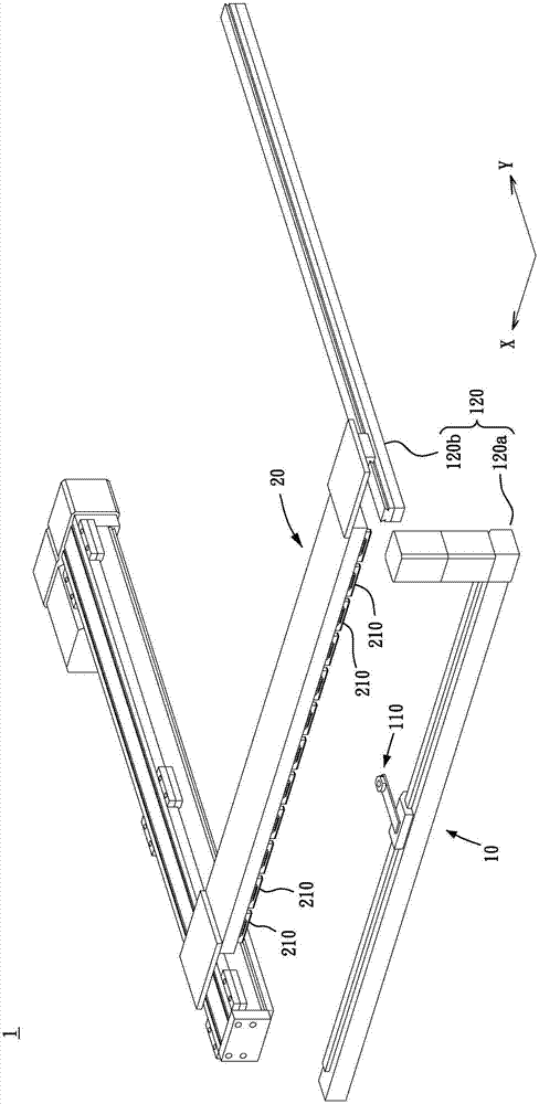
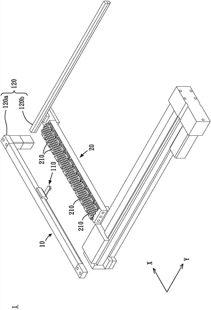
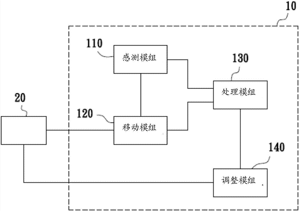
[0035] see Figure 1a and Figure 1b , is a perspective view of an exposure machine provided with the luminescence uniformity correction device of the present invention at different viewing angles. One side of the exposure machine 1 is provided with the luminous uniformity correction device 10 , and the luminous uniformity correction device 10 uses a sensing module 110 to target a plurality of light-emitting units of the light-emitting module 20 of the exposure machine 1 210 for detection, and for the light intensity adjustment operation of the light emitting unit 210 to ensure that the light intensity produced by each light emitting unit 210 is consistent, so that the exposure machine 1 can uniformly perform an exposure on an...


PUM


Abstract

The invention discloses a luminous uniformity correction device, which is suitable for correcting the luminous uniformity of a light emitting module of an exposure machine. The light intensity signals are generated by the sensing module at each sampling position corresponding to the distribution of the light emitting module, and the processing module analyzes the light emitting uniformity of the light emitting module according to these light intensity signals, and when the light emitting uniformity of the light emitting module does not meet the A corresponding calibration signal is generated when a uniformity standard is used, and the adjustment module correspondingly adjusts the luminous intensity of at least one of the light emitting units of the light emitting module according to the calibration signal. Therefore, by using automatic equipment to correct the uniformity of the light emitting module, it is possible to quickly and conveniently adjust the areas with abnormal light intensity to ensure uniformity of light emission, thereby improving the manufacturing yield of the circuit board.

Description

technical field [0001] The present invention relates to a calibration device and a calibration method, and more particularly to a calibration device and a calibration method for luminescence uniformity for calibrating the luminescence uniformity of an exposure machine. Background technique [0002] At present, the industry generally needs to use exposure machines when manufacturing circuit boards, and more and more attention is paid to multi-light source exposure machines with light-emitting modules composed of multiple light sources. Generally speaking, the light source of the light-emitting module is composed of multiple light-emitting Diodes, but due to the different characteristics of these LEDs (such as process differences, different hours of use, etc.), the luminous intensity of each LED will be different, so that the light emitting module will not emit light uniformly, which will directly make the photosensitive The light energy absorbed by the circuit board is uneven...

Claims


Application Information

Patent Timeline
Patent Type & Authority Applications(China)
IPC IPC(8): G03F7/20
CPCG03F7/70075G03F7/70133G03F7/70191
Inventor 张鸿明
Owner CHIME BALL TECH
Why Eureka
Try Eureka